I recently completed my Ghostbusters ghost trap and decided to begin tackling a project I always wanted to do, my proton pack.
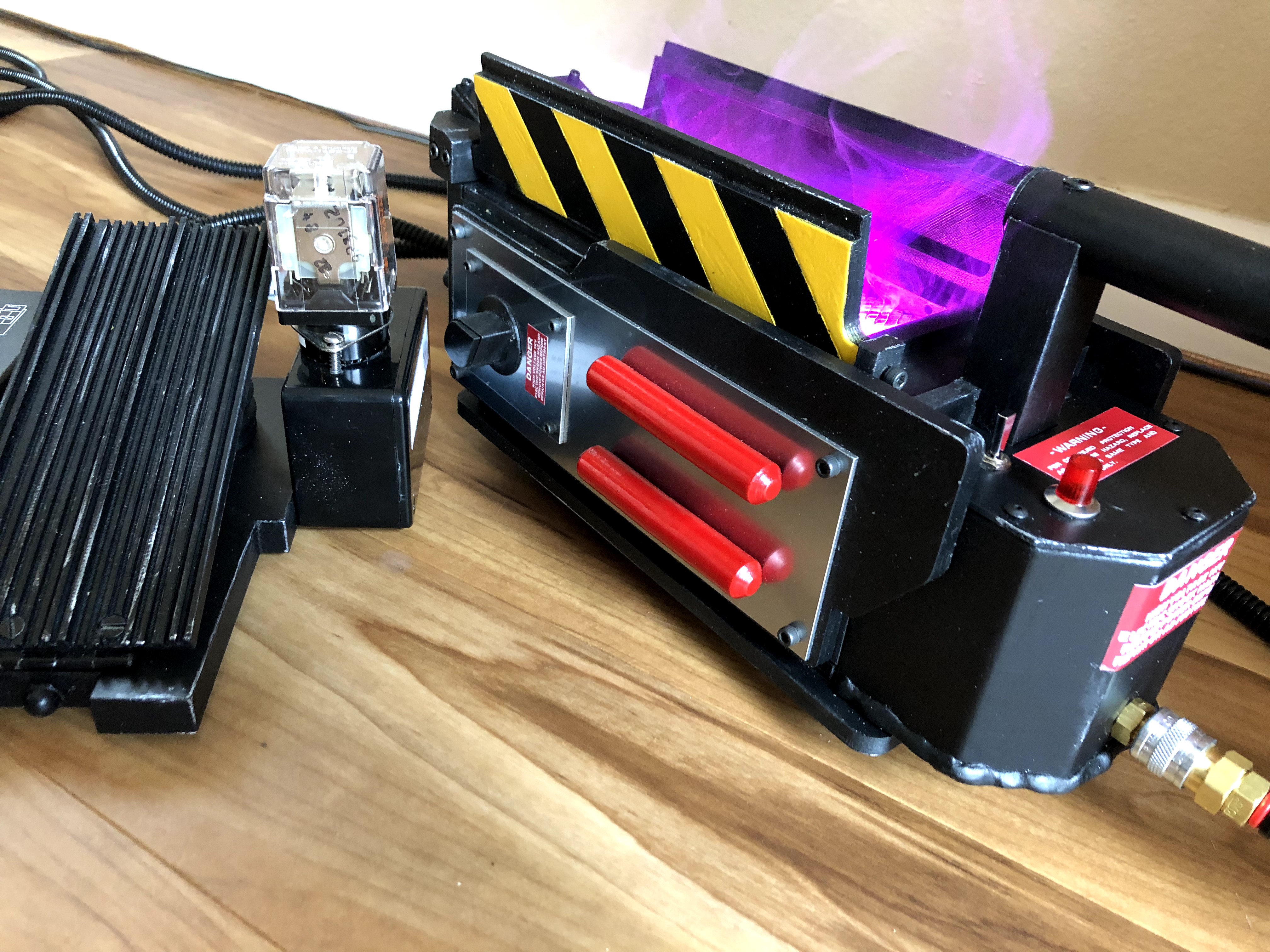
Warning! This is a verbose write-up that walks through everything I thought and did. It was written over multiple days as I actually did each step. Hopefully it helps someone and/or is fun, but don’t be afraid to skim :)
Making Plans
I used gbfans.com as my primary resource and researched the options available for sourcing parts. The use of real hardware, like knobs and screws, on the trap really made a difference, so I wanted to do as much of that as possible with the pack. The trap is mostly 3D printed on my little Maker Select (a Wanhao i3 Duplicator clone). The only large pieces that were not printed are the boxes on the pedal, which are two different Hammond project boxes, and the trap’s handle. I knew printing would be a part of this project, but I had to figure out how much I would print.
Gbfans.com has a wealth of information on different pack builds. Some people have made amazing packs using mostly MDF. Others have used only found parts or gone as far as creating or commissioning screen accurate aluminum pieces. Some builds use PVC, ABS, electrical conduit, and various other materials. The biggest problem with all of this information is many of the write-ups on these builds relied heavily on pictures to explain some aspects of the related projects and Photobucket, the image hosting service used by many of them, shut-off third-party image hosting at some point. Many threads now are now posts light on words and heavy on dead image links. The good news is enough survived to give me an idea of what I could use for different pieces of the pack. The gbfans.com site also has an excellent reference section full of screenshots and photos of the real screen-used packs on display in Sony’s lobby and Planet Hollywood locations.
The MDF and wood builds I have seen are beautiful pieces, but I nixed that idea early on due to concerns with weight. I decided my goal was to make this comfortable to wear for long periods of time and easy to mount on a wall. A finished pack is likely to weigh enough to feel hefty just with the combined weight of the pieces, electronics, and the ALICE frame it would be attached to. I shifted my plans in the direction of using a shell with real hardware attached to it.
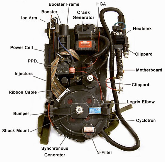
The pack’s parts have various fan-created names that help keep track of everything.
I learned about a great vacuum formed shell from Studio Creations and ordered one. I picked up some 1/4” plywood to make the “motherboard” to hold the shell and, eventually, mount the electronics. The shell is accurate to Stefan Otto’s proton pack blueprints available on gbfans.com and covers many of the large pieces, like the “gearbox” and the cyclotron. When I checked the measurements the only issues I found were minor and probably a result of the vacuum forming process creating some curves where there should be sharp 90 degree angles. I also ordered Clippard hex fittings, Legris elbows, tubing, and a few other small accessories from gbfans.com. I used the site a lot for reference materials, so I wanted to support the site – and make my hardware shopping easier on myself as a bonus.
Next I had to determine how I would create all of the little pieces, including the Hydrogen Gas Accelerator (HGA), Ion Arm, Booster Tube, cosmetic plating, and the rest. A lot of these are pipes and tubes of various diameters and lengths, so I took the measurements from the plans and returned to the hardware store. I visited my local stores and came up empty handed. None of them carried pipes or tubing of the correct outer diameter for properly sized pieces. I was really out of luck for pieces like the Booster Tube which uses 2.5” OD aluminum tubes. The stores had the tubes, but didn’t have much beyond 1 3/4” or 2”. At this point I started calculating the cost of sourcing all of these pipes and caps/lids for them from the internet and started looking at my 3D printer.
I had a few things to consider. You can make some rock solid and strong pieces out of PLA, so I was not worried about anything breaking or being too brittle. My biggest concern was heat. If my pack contained a lot of PLA pieces I would never be able to leave it in the car on a hot day. That could be a factor at some point. If I forgot about the PLA, then that day would be a sad day. On the upside, cost and weight were big pros. For the cost of one or two of the harder to find hardware pieces, like some of the rarer vintage 1980’s pieces, I could buy enough PLA to print a whole pack. Also, I could always reprint the pieces later in ABS which has a much higher melting point. I say later because I still have not tried printing ABS and didn’t want to jump in head first on this project.
With that in mind, I also made it a priority to make the pack modular. This would make it easy to replace broken pieces, replace pieces with more accurate/upgrade/improved parts or ABS parts, and simplify installing electronics at a later date.
I decided to begin by reviewing readily available 3D models, of which there are plenty, to start the process of finding and creating the perfect ones for my pack.
3D Printing Parts
You can find dozens of 3D models for every piece of a proton pack. You can even find packages of models to 3D print everything, but they are not all created equally. A lot of the models are more best guesses than accurate models and some people forget to mention they have reduced their parts. One of the most liked and “collected” proton pack models on Thingiverse is a collection of models that are more rough sketches or silhouettes than accurate representations (the Clippard valve is a cylinder on top of a larger cylinder without any of the details).
A lot of the accurate models I found were scaled down because the modeler was smaller and wanted a slimmer pack or the pack was being printed for a child. I experimented with scaling some of the reduced parts as test pieces, but a lot of these smaller parts had holes sized for the correct screws and scaling up the size increased the hole size to the point that I would have needed much bigger bolts and screws.
I eventually found a few pieces that I really liked and then realized they were all made by the same user on Thingiverse, tgoacher:
https://www.thingiverse.com/tgoacher/designs
This modeler put a lot of thought into his designs. The larger pieces are broken up into smaller pieces and cleverly pieced together using #4 screws. He also sized everything to Stefan Otto’s blueprints. I used his models and designs for my pack’s Injector Tubes, Ion Arm, HGA, PPD, and Booster Tube. My only complaint was some of the tubes had a lower polygon count which gave the tubes some flat edges. This was easily fixed during the finishing process and the design were/are great, so I didn’t bother making my own models. I wanted this pack to my own, but I’m also not one to reinvent the wheel.
Note: In the final stages, I ran into some slight snags using real hardware with Tgoacher’s models, but the models are still great and the issues were easily resolved. The models are just meant for a fully 3D printed pack and lack some of the necessary holes or have holes meant not meant to accept the full-sized, real hardware threads.
I’m a novice 3D modeler, so small and complicated objects are daunting. I found some models for these pieces. For the crank knob, I found a lot of options, but only one really looked like the real deal. That model was made by Slicerd on Thingiverse:
https://www.thingiverse.com/thing:2286300
It looks like it has the right curvature on top, a good amount of the scalloped knob is shown, and it has set screw holes. These are all details and features other modelers got wrong or left out. I was really happy with this one. I also needed models for the little resistors. I found another user, Agmeadows, had some great models:
https://www.thingiverse.com/thing:2609007
https://www.thingiverse.com/thing:2608995
https://www.thingiverse.com/thing:2609016
The final prints looked great and very close to the real thing. They just lacked the little wires and tabs / soldering points sticking out of the sides.
Editing The Models
In most cases, I did not edit the models I used from Thingiverse. I loaded them into Simplify3D, checked the sizing against the plans, and printed. There were some cases where modifications in Simplify3D helped me template the pack connections, drilling, and cuts. A good example is the Ion Arm. Tgoacher included holes for screws in the bottom of the model. I loaded the bottom piece into Simplify3D and printed it, but for this print I oriented the model so the bottom (with the screw holes) was against the print bed and printed just the first 0.5mm of the model. This created a perfect template to tape to the pack for pre-drilling the holes.
Making Custom Models
The pack is made using a lot of basic shapes, so many of the pieces are not too difficult to model. I started by making perhaps the simplest pieces, the cosmetic plating for the Sychronous Generator, aka the bottom of the pack.
Stefan Otto’s plans show the plating is 2.5” long, 1.547” wide, and 0.125” thick. There are fourteen plates in total. Four of these are special. One of them attaches at the very bottom center and is 0.5” thick. Another is on the left with a block that has holes for the tubes that attach to the Injector Tubes. The other two are 0.5” shorter than the rest and go at the ends of the string of plating, one for each side. It would be simple to cut these out of something like basswood, but I used Onshape, a free online CAD application, to make these designs for 3D printing. Whether I used wood or PLA, printing one of each plate would help outline my cuts.
I would need two short plates, eleven standard plates, one fat plate, and one box for the tubes.
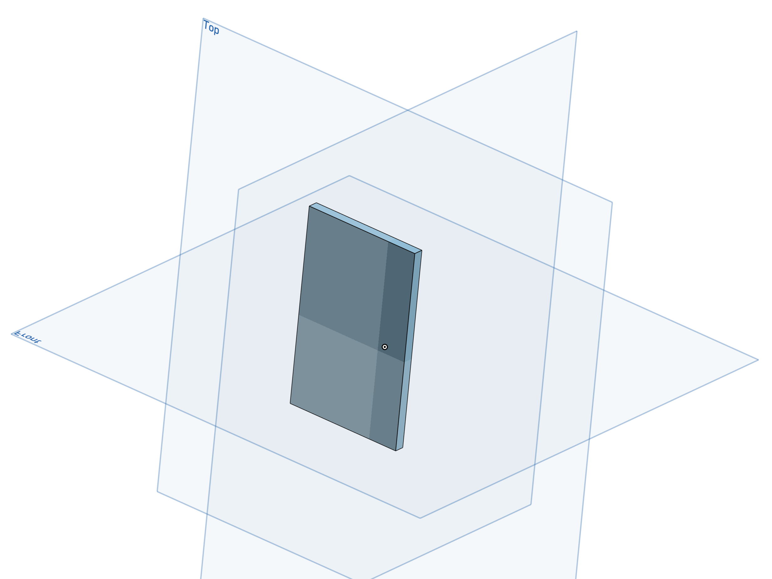
Here is one of the standard plates, a basic rectangle extruded to 0.125”.
Making a shape and extruding it to the proper thickness is just about the easiest thing you can do in Onshape, so this was quick. Simplify3D estimated the cost of printing all of my plates would be $3.56. Not bad, especially when it saves me time cutting and sanding! I opted to go this route instead of using plywood or basswood. The PLA would be less likely to crack or break, and if it did it would just reveal some black PLA instead of wood and go unnoticed. I made up the plates I would need and then created a plate with a hole in the middle for the 3/4” wire loom hose connecting the pack and the gun.
The last thing was what I refer to as “the tube box” for one of the plates. The plans show the box isn’t a simple rectangular box. It’s 2.250” long on the bottom and 1.961” long on top. The side facing out from the pack (away from the motherboard) has a slight angle. Also, exact measurements for the holes were lacking. The plans show the center of one hole is 1.00” from the motherboard and the next is 1.625”. Each hole needs to accept 1/4” OD tubing, so I went with 0.250” holes with centers at those points.
What I did was create the box and then applied a chamfer to one edge. In Onshape, I set the chamfer to “Two Distances” and provided 0.5” as distance one (the full thickness of the model) and 0.289” for distance two (the difference between 2.250” and 1.961”). Then I created the two 0.250” circles and used the dimension tool to set the centers at the appropriate distances.
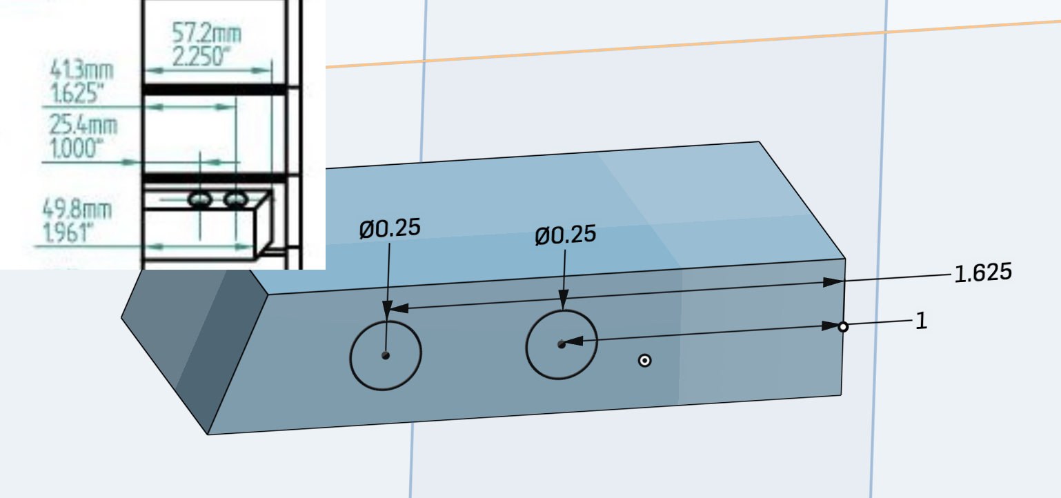
The sketch looks “squished,” but the dimensions are clear. This model appeared to match my reference photos and the dimensions matched the plans, so I was happy.
Next, I modeled some caps for 1” ID PVC tubing. I ended up using this tubing for the two tubes on the “cosmetic plating” in the middle of the pack and the vacuum tube. I modeled the caps to fit inside the tubes and extend to the edges. I left left all of the edges squared, i.e. no chamfers or rounded edges, and made the top just 0.125” thick. This made it easy to subtract 0.25” from the measurements for the tubes when cutting them. I duplicated this design and added a 0.375” hole through the center. This model was used for the bottom of each tube to bolt the tubes to the pack and the top of one tube to accept a Clippard hex fitting.
I later realized that 0.375” bolts were just bigger than required and I was using M6 bolts elsewhere, so I made an M6 version, too. While testing assembly, I also found glue was insufficient if I was too forceful while screwing on nuts. I added holes for the bolt heads to fit into and prevent the bolt from spinning inside the tube during assembly.
I made an additional PVC cap for the vacuum tube. This one had a 3/4” hole, a 1/2” insert, and would not be glued into the pipe. This enabled me to slide the wire loom through the cap, secure it, and then insert the cap into the tube. This way, the wire loom would still be removable, as needed, without having it fall out of the tube or need to be glued.
Finally, I modeled my N-Filter. This piece requires making some decisions. The first decision was made for me. My model would be a whole cylinder, not one cut to fit over a cyclotron. My shell has a space for the N-Filter, so that design would not be necessary. Next, the screen-used packs have uneven holes that are probably the result of someone making a small mistake in their measurements and drilling during prop building. You can divide 360 degrees evenly into nine 40 degree segments. The screen-used filter has eight holes that are 41 degrees apart. This leads to uneven spacing. On one hand, I would duplicate this if I was making a screen-accurate hero pack, but this is my pack and I would like to think Egon Spengler would have noticed and corrected this error for future pack manufacturing! He just doesn’t seem like the type that would get sloppy with details like this.
I went with nine holes at 40 degrees. I made the N-Filter solid at the bottom and hollow at the top with 0.25” walls. The wall thickness was just a good balance between thin enough for it to be believable as aluminum tubing and thick enough to make the print easy and strong. At this point I made two versions of the filter.
Originally, I left the top open and finished the main body by reducing the size from 3.625” to 3.5”. I made a 0.125” thick cap that would be glued on later. I designed it this way so I could easily paint the inside, as needed, and insert wire mesh and wax paper (more on that later). The last piece was adding holes in the bottom and the side to accept #4 screws for mounting to the pack. I would have gone with a bolt, but I wanted at least two points to prevent the N-Filter from rotating and it seemed prudent to also insert a screw from the side to help with it being pulled down and away from the pack.
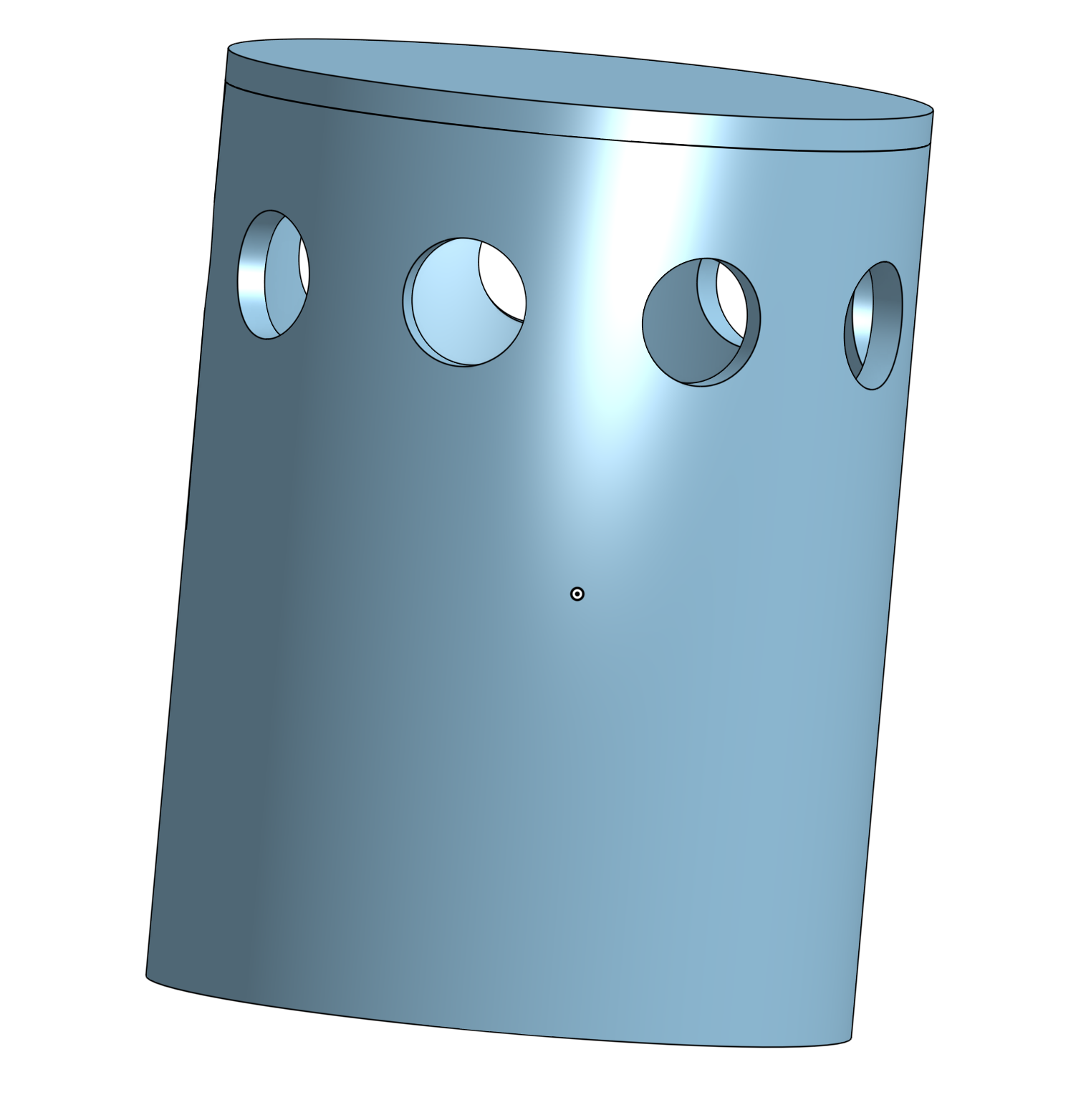
Original N-Filter design with the top attached and a mostly solid body.
Then I considered a model that would be entirely hollow. This would allow for inserting electronics into the N-Filter from below. In the movies, the N-Filter is just a filter. It does nothing fancy. However, the video games show the N-Filter lighting up and smoking. It’s a neat effect and, while I wasn’t expecting to do this, I thought it might be nice to have the option. I did intend to add smoke effects to my pack and the N-Filter with it’s open design and mesh at the top offers a convenient location for smoke to escape the pack without needing to drill holes elsewhere. Also, as a bonus feature, it would print much faster and would not require gluing the top.
The challenge was designing it so that it would be easy to print as a hollow object. I made a reversed version of the original model with the hole going from the bottom to the top. Easy enough and it can be printed upside down, but a mounted N-Filter has a slight overhang. To account for this, the walls could be made thicker, but I liked them at 0.25”.
Note: After printing this I learned the 0.25” walls are plenty to account for the overhang. I still think this next part is helpful for securing the N-Filter to the pack.
Riffing off of Tgoacher’s HGA design, I created a 2.5” insert with an offset 1.5” hole. The insert was designed to be slid into the N-Filter body without glue. The filter is attached to the pack on the sides and the bottom. The screw in the side prevents the filter from being pulled off of the insert and the screws in the insert prevent the insert or filter from moving around. There’s no need to glue the insert because friction will already keep it tightly in place and the screws do the rest. This way the insert can also be easily removed if I ever need to fix the wire mesh or anything like that. The hole would allow for wiring, if needed, and works to offer something to pull to remove the insert.
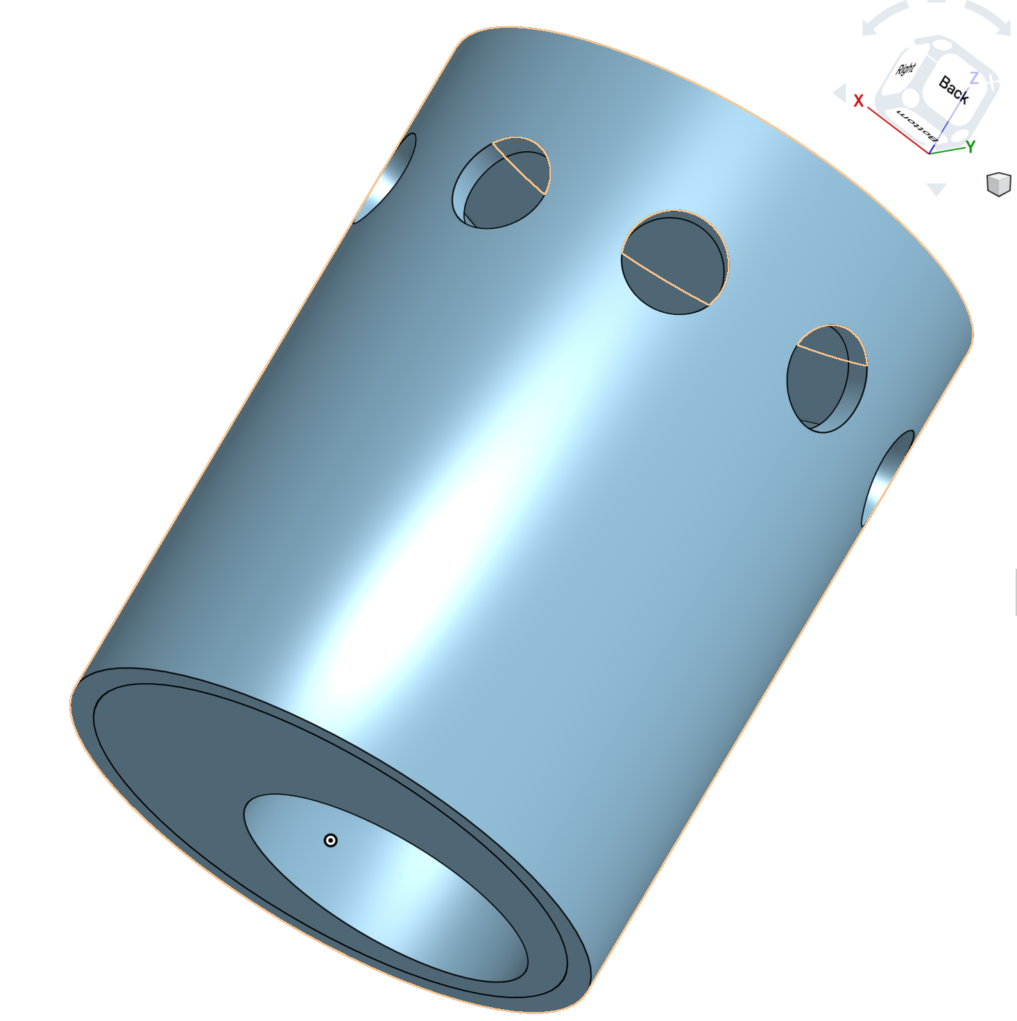
Alternate design with a hollow body and insert to allow for faster and easier printing and electronics as desired.
The parts can be found on Onshape, here:
https://cad.onshape.com/documents/2e9f8d87e4bb511a32ed2d57/w/c7f374eb1d7e4cc0102cba16/e/bad2f51a61784ff425898087
Printing The Parts
Printing was straight forward. I loaded the models into Simplify3D, checked measurements, and created the gcode files. I didn’t do much to prepare the models beyond tweaking support settings and orientation. The parts needed to be durable, so I printed them all with three shells and a minimum of 20% infill. The number of shells and the printing orientation control the part’s strength. Infill was increased for parts that would take wood screws during assembly or might need more for supporting top layers and features.
I oriented the parts to reduce print times and support material requirements. Very few of the parts would be load bearing, but long/tall part that could be printed on their sides were printed in this orientation so they would stand up to bending. Think about this like wood grain. It’s much easier to snap a board in two when you bend it with the grain.
I printed most everything at 0.2mm resolution, but I printed some small pieces, like the resistors and crank knob, at 0.1mm. I printed these at a higher resolution to improve detail work on the little ridges and scalloping and reduce layer lines. These small pieces are much more difficult to fill with putty or resin and sand without harming the details you actually want and doubling print time wasn’t a big deal for these little pieces.
Overall, print time for everything was a little over 50 hours. Total printing time is probably closer to 65 hours with my test prints during the design process and some pieces I screwed up while testing assembly.
Preparing The Prints
While reviewing other proton packs – and numerous other 3D printed models and props on the internet – I often see a lack of finishing work. Look at pictures of the finished models linked above and you can tell they were printed. From a distance they look good. However, you can see how the layers of the print and little imperfections really shine in certain light and when viewed close-up. These little things often become even more pronounced once painted. The paint – even flat paint – tends to seep into imperfections, accentuate layer lines, and highlight misprints. All of your hard work painting (and painting really is the way to go; not just printing with a particular color filament) and assembling a prop is quickly undermined by skipping the most important and first step: filling and sanding. Just like the process of printing the pieces, a good foundation is key for the rest of the paint job.
The finishing work is not as daunting as it seems. If you search around for articles on finishing PLA, you find a lot of mediocre advice about sanding, a lot of sanding. Bill Doran has an excellent video that covers the sanding and filling process I typically use for 3D prints:
I use Bondo spot putty on my prints. A 16oz tube cost me $20 on Amazon a while back and this pack build finally made a dent in it. I have about half a tube, ~8oz, left and I used it liberally on this pack, the ghost trap, and a few other small models. A little goes a long way, so these tubes last a while. You just need to take a little bit and spread a very thin layer across the print surfaces. This is really easy on flat areas. For small areas, you can use a little spudger, X-Acto knife, or some other make shift mini putty knife. I use the spudger and opening tools that iFixIt and other companies offer for opening electronics like phones. They have small points and skinny and narrow flat edges that work well for getting Bondo into tight areas.
The putty gets into the little gaps and in-between layers and cures within 30-60 minutes. I often let it sit for just 30 minutes before I start sanding, if I’m feeling impatient. The thin layers cure fast. Then some light sanding with 150 grit sandpaper leaves the surface slightly pink and smooth to the touch. It won’t look like much at first, but it will feel smooth. Once you apply some primer you will really see the results as the paint covers the plastic and pink putty in one smooth color.
Bondo is a resin that dries hard. It’s meant for doing exactly this, repairs, but it’s made for big jobs, like vehicles. Using it on a 3D print is the same idea on a small scale. It adds a really nice surface to the print and probably adds some extra strength to the shell as a bonus.
Note: Using a resin like XTC-3D is also a good option. It won’t fill-in gaps or holes like Bondo, but does ooze into all the little layer lines and imperfections on the surface of a print and it can be easily sanded. I use this on prints that are already smooth or really small. The downside is it needs to be mixed in small batches due to the short working time, is kind of messy, and adds material to the print. That last one can be trouble if pieces need to fit together in a very particular way. I didn’t use XTC-3D on the pack because I was already working with Bondo and didn’t think mixing up a lot of XTC-3D to cover the large surfaces of these prints would be any better than using the putty.
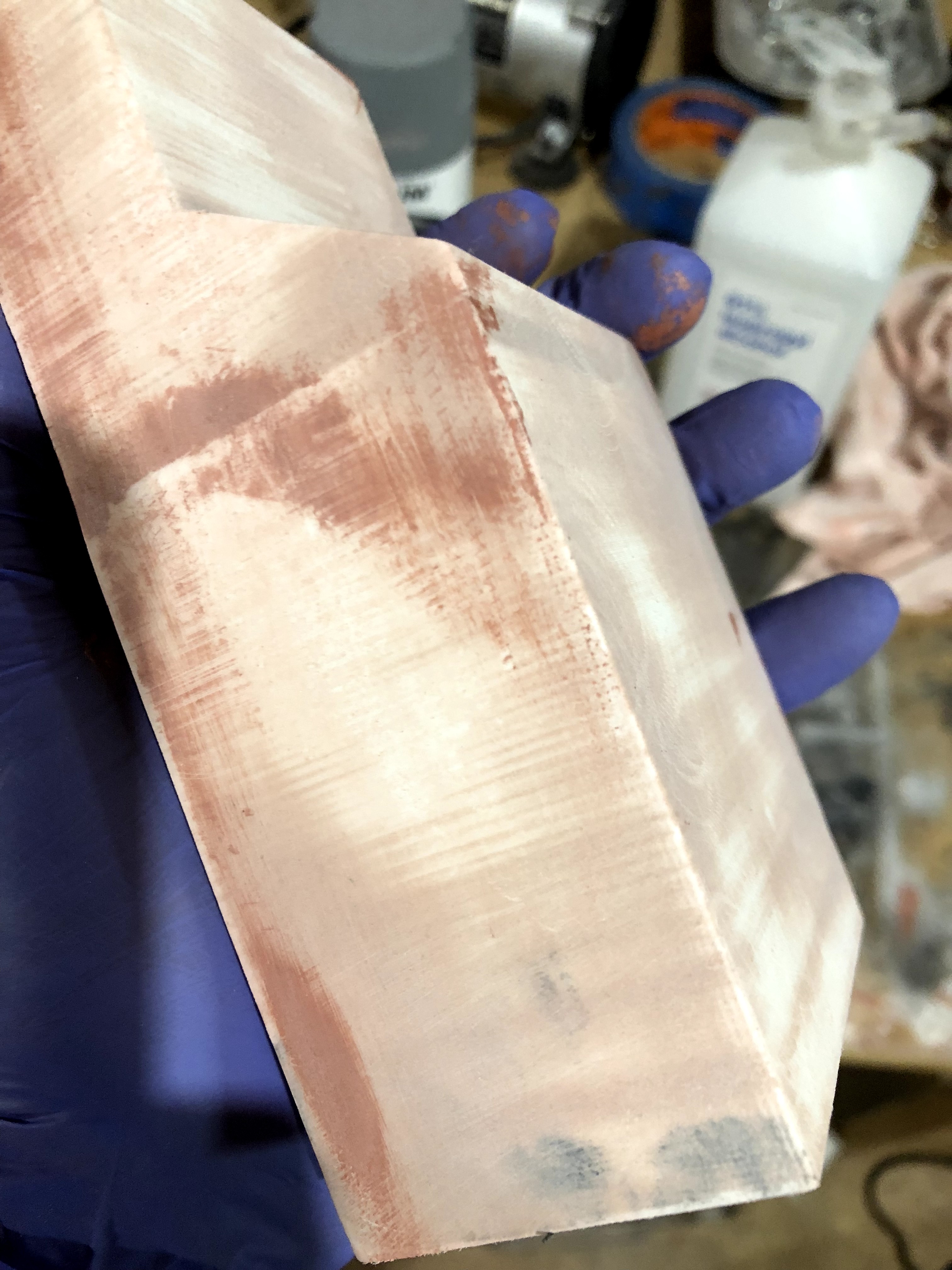
It still looks rough, but it’s smooth to the touch and a huge improvement!
My Ion Arm is two pieces screwed together, so there were lines that I wanted to hide. There were also other issues I hoped to repair and hide. To use one of my favorite Adam Savage phrases, I needed to hide my crimes.
It may not look smooth in the picture because you can see the pink putty and white PLA below it. You can see some of the layers and it seems unimpressive. However, here is a quick note on this piece. My 3D printing went terribly wrong on this day. I noticed my pieces were not looking their best, but I was not in the mood to try re-leveling a print bed and the prints were looking good enough for this work. Unfortunately, the root cause turned out to be a clog in the print head and I printed every piece of the Ion Arm together in one plate, overnight, for 14 hours. The clog worsened over this long print job and resulted in a print that looked alright for the first third or so and then deteriorated. There were gaps in the sides and the top layers were messy.
Note: I figured out it was a clog after this print. I foolishly ignored the previous print’s less than great results, suspecting a temperature issue. The previous print just had some not-so-pretty top layers. After the Ion Arm I gave the printer a check-up and everything seemed fine. Then I tried printing some tubes for the cosmetic plating and I ended up some solid 2mm thick rings and the rest of the tubes looking like they were made of spider webs. That was when I knew it had to be a clog and it took me less than two minutes to resolve the problem with a 0.4mm drill bit and a little push.
Thankfully the clog only got really bad after the Ion Arm print and this print was still quite solid through and through. I combined the pieces with #4 wood screws and mixed up some Bondo body filler to cover the combined Ion Arm pieces. I waited 30 minutes for it to cure and then aggressively sanded it with 80 and 150 grit sandpaper and my Dremel rotary tool. The result was a much nicer piece with the gaps filled in with Bondo (the tan colored areas). Then I did a pass over a few of the remaining issues with the spot putty (the pink areas). Again, I waited for the putty to cure and sanded it smooth and level with the rest of the surface.
The next step was applying the primer. I cleaned the surface with rubbing alcohol and a rag and used a spray can of automotive filler primer. Filler primer is awesome for prints that don’t have tiny details. As the name implies, it fills gaps. It’s meant to fill little scratches before you apply paint, so it does the same thing on the models. It fills in scratches, small gaps, and the like. I used that on pieces like the Ion Arm, HGA, Booster Tube, and other big things that didn’t have small details I wanted to keep.
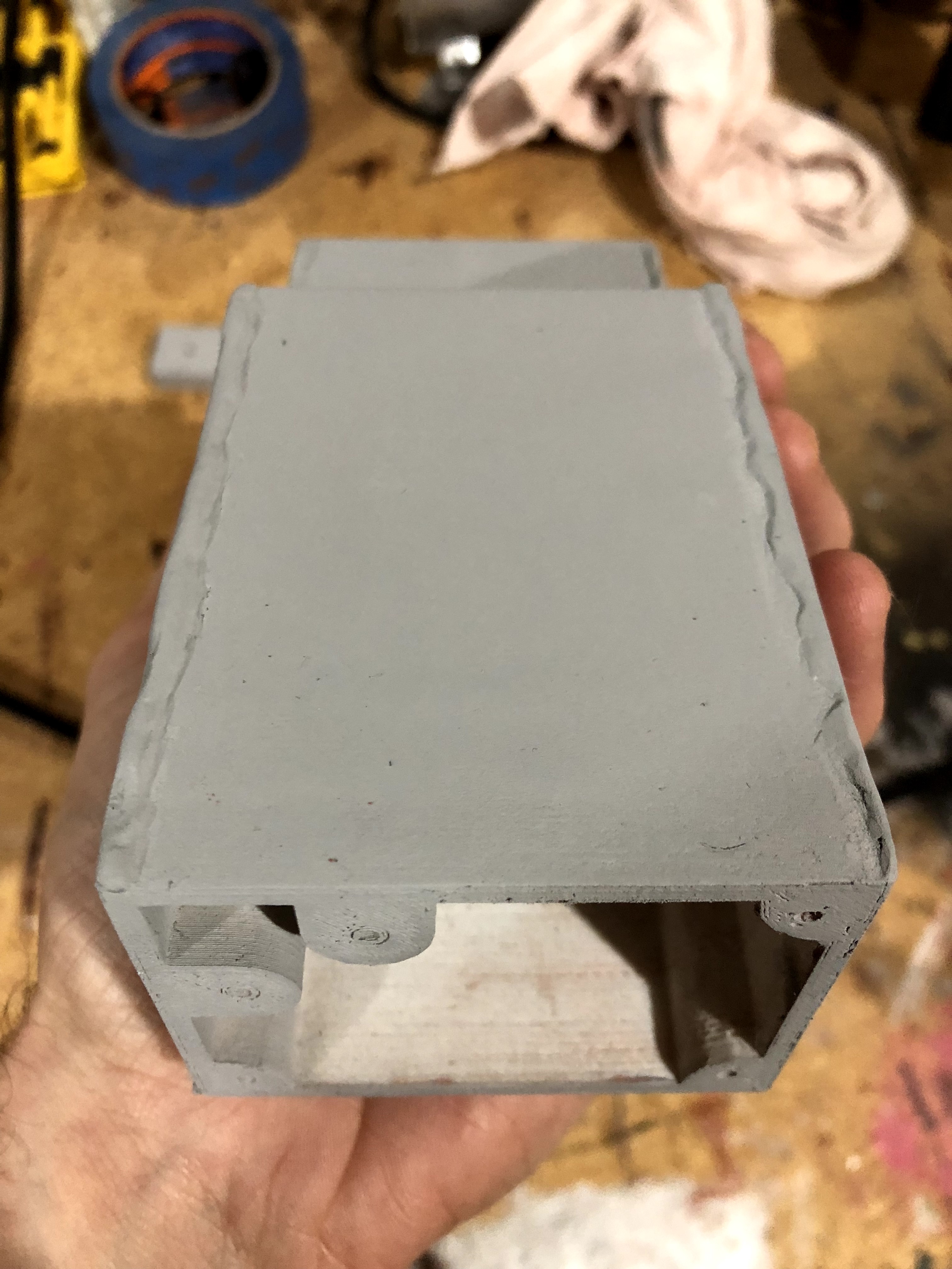
No layer lines or gaps here.
Here is the primed Ion Arm. I also added some plumber’s epoxy putty to the edges for the weld line effect. I took the picture at this angle to showcase the difference between the new surface and what lies underneath/inside. The difference is remarkable and well worth the effort. In this close up, you can make out some small imperfections on the outer surface, but they were nearly invisible to my eye (I couldn’t even see them until I reviewed the picture, honestly) and I couldn’t feel them. They would also disappear in the flat black paint at the end of the build, so I was very happy with this surface for the next part.
Note: Long after I created my “weld lines” on my parts, I stumbled into a tutorial hidden in a somewhat unrelated forum post. What I did was roll out the epoxy, lay it on the part, and work it to stick it to the part and try to mold it. This worked and the finished and painted effect looks good, but they don’t necessarily resemble real welds on close inspection. Also, these worms of epoxy would start to stick to my nitrile gloves and keep pulling away from the part. That was obnoxious when trying to wrap it around big pieces like the N-Filter. I had seen better weld lines around The Replica Prop Forums and other places, but never found anyone explaining their steps. This tutorial recommended doing what I did, but then cutting the roll into little chunks. The next step involves taking one chunk at a time, pushing the chunk into place, lifting your finger away, and placing the next chunk overlapping the previous one. By pushing it into place with your finger and lifting away, the chunks begin to form a more realistic looking weld line. I’ll definitely follow this tutorial’s advice when/if I create new parts and when I complete my wand.
At this stage, I sanded the primed surface using my Dremel. The primer helped identify areas where there were gaps in the epoxy putty or scratches/gaps on the surface that could not be seen in the sea of white, pink, and tan. Primer is great for this. It reveals all these little things you would never notice on the print. This is one reason why I always prime my 3D models before painting, even if I will be using a spray paint that says it includes primer. Primer also helps smooth out the surface and increases the bond between your paint job and that surface. Primer dries quickly and will be worth the effort in the long run. It’s also the way to get a perfectly smooth untextured surface for parts you want to look like machined metal.
I applied a couple more thin coats of primer and then used 200, 600, and 800 grit sandpaper to smooth the primed surface. This process smoothed the overall surface and left me with a nice surface ready for painting.
I will focus on the progression of the Ion Arm going forward, but know that this process was repeated for each of the other pieces, e.g. the HGA, Booster Tube, and so on. I just didn’t need to use body filler for those pieces.
Metalizing The Prints
I utilized an old trick involving multiple coats of paint to achieve a weathering effect on my parts. I used my airbrush and Model Master’s Aluminum Plate (Buffing) paint to make the pieces to look like aluminum. These paints are a lot of fun because you get to see your hunk of plastic transform into metal. The pieces looked good after buffing the aluminum. I then sealed this coat using Model Master’s metalizer sealer. This was an important because it prevented this layer of lacquer from being harmed during the next part. Also, because these are lacquers, they dry really fast (10-15 minutes).
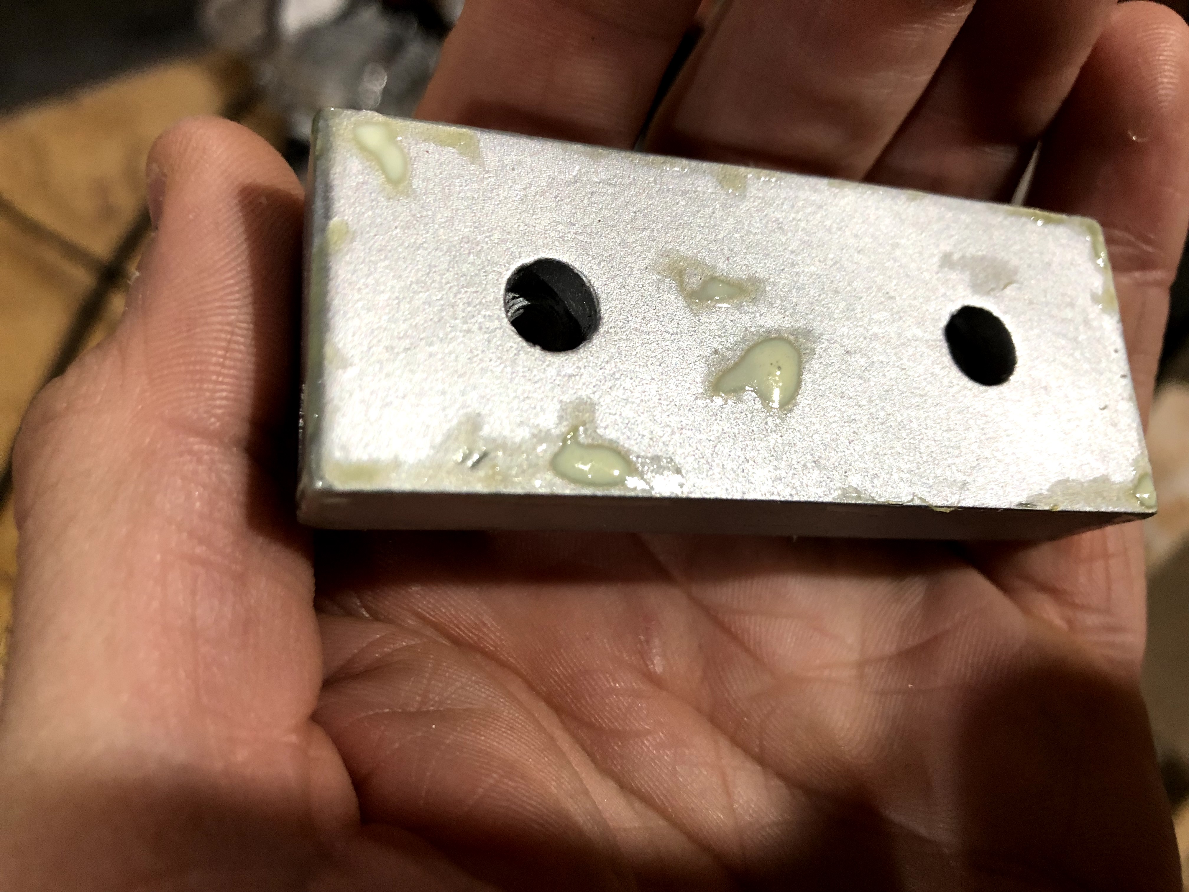
I just gooped the masking fluid on here to make sure I could see where it was later and get a grip on it to pull it off.
For this next part, you can use toothpaste or even mustard. I have used mustard before to great effect, but a tip from Bill Doran of Punished Props introduced me to this latex masking fluid, available on Amazon for $11. I painted it on wherever I wanted the black paint to peel away. The Ion Arm top is pictured here with the masking fluid liberally spread around it. This piece is really banged up in reference photos, so I went nuts with it. Once dried, it temporarily sticks to the part. When I was ready, I scrub at the masking fluid with an old toothbrush and my fingers to peel and rub away the rubber for an amazing weathering effect.
Note: In the above close-up shot, you can really see the texture of the piece. On one hand, it looks like metal, but that texture doesn’t sell it as machined metal. I would have had to sand the last coat of primer more for a smoother finish. The truth is… I forgot. I had to leave my work in progress and forgot I was about to sand the pieces. I came back to my shop and started masking. Oops! Fortunately, it doesn’t really matter for the proton pack. I want texture appearing on the flat black paint and the metallic finish is only meant to peak through. Just remember it’s important to keep sanding as much as you can stand if you really want/need a machined metal finish. This was important to remember when I finished my gun hook and a few other pieces that would not be black.
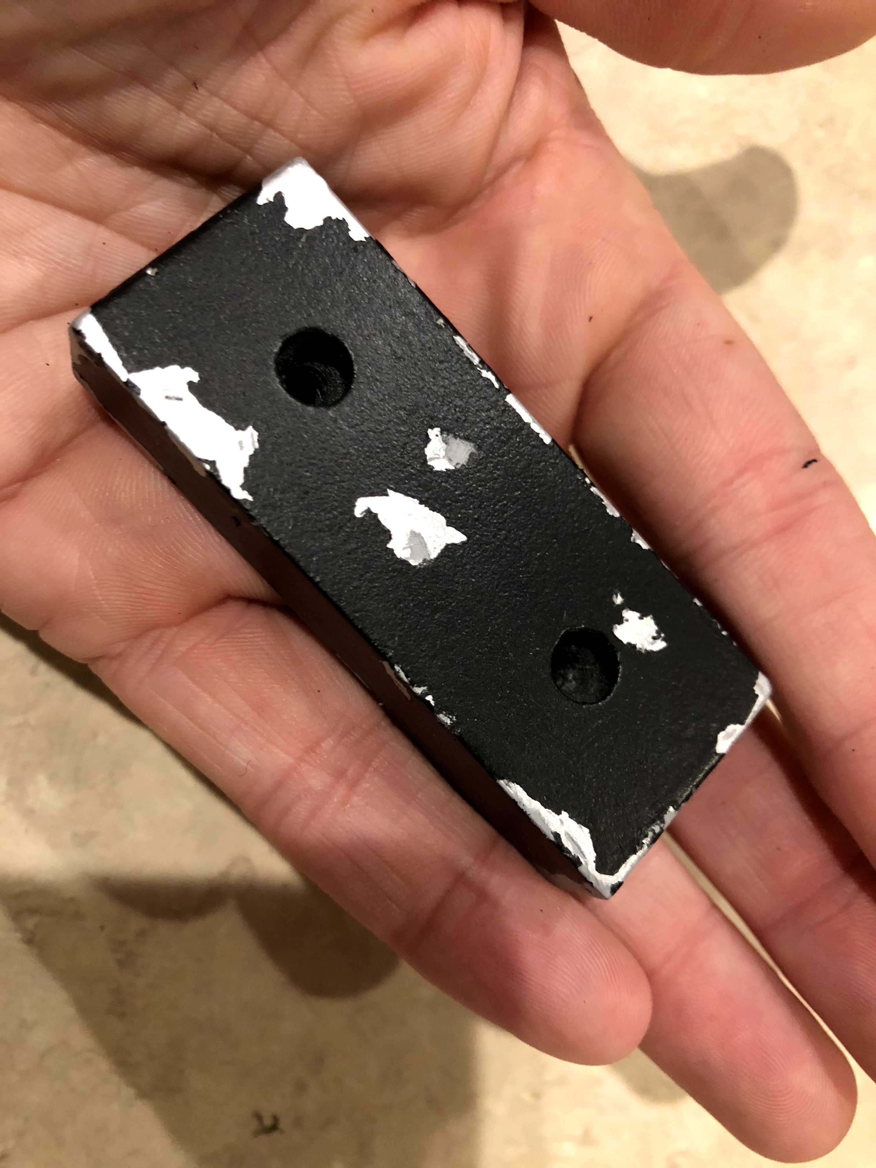
I accidentally made the aluminum underneath look banged up and scuffed and I was pleased with how it looked.
Then I spray painted the pieces using multiple thin coats of Rustoleum flat black paint. This involved more spraying, but the thin coats dry faster so I was able to get to the best part faster. Once I was done, I sealed everything using flat top coat. I did this before pulling off the latex mask because I didn’t want the “metal” to get hit with a matte finish.
Finally, I pulled off the latex mask to complete my beat-up-proton-pack look from the movies. There’s something to be said for “brand new” looking prop replicas, but this is my favorite part. None of the Ghostbusters’ proton packs looked pristine, nor would a pristine pack look that way for long, so I looked forward to this during the build. This also helps sell these white and black plastic parts as aluminum parts painted black.
Note: Some of the metallic areas appear dark grey and I can’t explain that. I lightly scratched at one and it appeared to get lighter, so I don’t think it’s the primer. It might be, though. I left this piece sitting for a while after being called away from my shop and I believe I left the masking fluid sitting on it too long. It either lifted off the lacquer finish and lacquer paint (I didn’t notice any paint coming off with the latex, so I don’t think this is the case) or the latex stained the finish. I believe the latex stained the metalizer sealer because I only had this happen on the pieces that were air brushed and sealed with this sealant. I could have painted over it and tried again, but I actually liked the effect. It made everything look more banged up and natural.
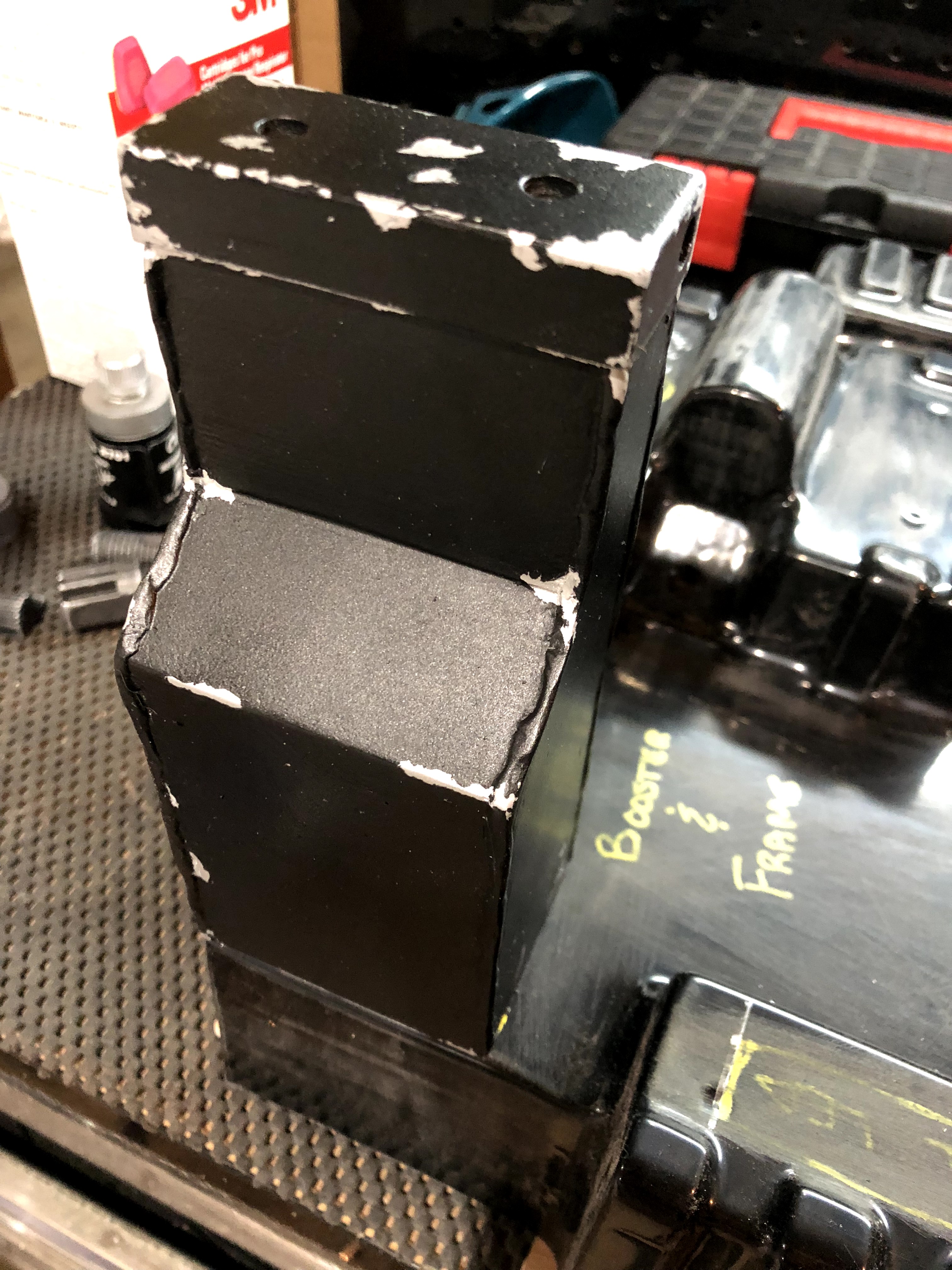
I was really happy with the paint texture and the contrast with the airbrush paint below it.
Here is the assembled Ion Arm (sans resistors and other bobbles for now). To finish the weathering, I very lightly hit the edges with silver rub n’ buff. I just took some out of the container using a clean soft rag, rubbed it onto my work surface so just a little was left on the rag, and lightly (very lightly) ran my finger along the edges. This gave the piece that slightly scuffed look, as if metal was peaking out from behind a black finish. I still can’t decide if I went too crazy with the weathering or not, but it looked good sitting on the shell. My thinking was a piece like this sticking out away from the pack and being on the side would get knocked around quite a lot when you see the sorts of things the Ghostbusters go through in the movies and cartoons.
For unlicensed nuclear accelerators, the packs aren’t treated with much care. In the RGB cartoon, they’re practically disposable and have a self-destruct function! ¯\_(ツ)_/¯
Again, this process was repeated for other pieces. I placed everything on my shell and judged where the parts might become beat up or weathered. For example, the HGA was painted to be weathered on “top” (side with the Clippard and Legris connectors) where it faces away from the pack and on the “side” (with the M6 screws and label). The side facing the interior of the pack would be somewhat protected and was left alone (not to mention it would also never be seen once installed, so no reason to waste effort).
Making The Body
While I waited for parts to print and paint to dry, I worked on the shell. I lightly sanded the shell with 150 grit sandpaper, inside and out. This helped clean-up the little bits of plastic leftover from when it was cut after vacuum forming and to prepare the surface for primer. I then went over everything with my ruler and calipers to compare pieces to the plans and mark where I would need to drill holes or make cuts. I made marks with a silver Sharpie and came back later to drill the holes to the appropriate diameters using stepping bits.
Notes on Drilling Holes
Do not try to use Forstner bits on plastic. Use step bits for holes larger than a 1/4” drill bit. Trust me, I tried it once while constructing my trap and it was a terrible mess. I thought I could make it work if I was really careful, but it was an awful idea. I basically destroyed the piece but lucked out that my crime was conveniently hidden by another piece and you can’t really see the atrocious hole I made.
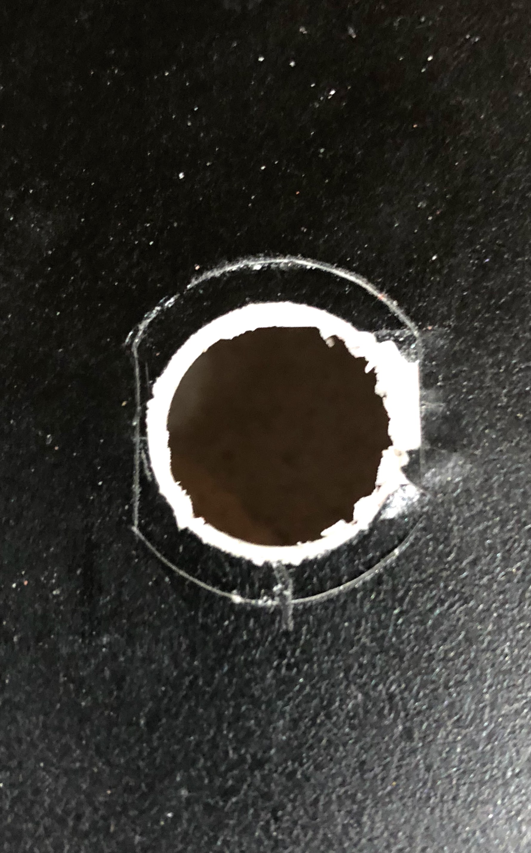
I could have just glued the resistor on without this hole. I really don’t know what I was thinking, doing this after I had painted everything.
I cut this hole using a step bit. Even with a step bit, cutting into the side of a 3D print means taking a chance you’ll ruin it. This is the attachment point for the PH-25 resistor on the Ion Arm. I started by tracing the resistor’s shape on the part. Then I lightly scored the plastic using a brand new, sharp X-Acto blade. I traced a circle the size of the hole I wanted and then really cut into the plastic with the knife to score it. This was to prevent the drill bit from breaking up the side layers and causing them to peel back and damage the part. This paid off in a big, big way. You can see it saved me some heartache on the right side where some of the PLA broke apart but snapped off at the score mark where it wouldn’t be seen.
I started the hole in reverse, i.e. the drill bit spun to my left without the cutting teeth. This started a 1/8” hole for me and then I switched directions and went very, very, very slowly. The hole looked good in the end, but this bowed out and messed up the interior wall’s layers. I used a heat gun to clean-up the exposed infill and the inside layers. A few quick sweeps caused these strands to melt and organize themselves. The end result was a clean hole I could insert the resistor into. This same process was used to drill holes in other parts and the shell for pieces like Clippard and Legris elbows.
Attaching The Shell
The next step involved finding placement for the brackets that would attach to the motherboard and shell. I used four L-brackets with #10 1/2” socket cap screws. The L-brackets I found had holes meant for #8 screws, which was perfect. I used a #10 tap to create threads through the L-bracket where the socket cap screws would be used to go through the shell and secure the shell to the brackets and motherboard. This was necessary because I needed the screws to go in and remain secure without nuts. Remember, the L-brackets can only be attached to either the shell or the motherboard with bolts and nuts because, once fitted together, the inside of the shell is inaccessible. In other words, the plan was for the brackets to be secured to the motherboard and then set the shell on top of them, obscuring the brackets and holes, to be secured with the socket cap screws.
That is the usual configuration for proton pack builds, but poses a challenge: drilling the holes through the shell to align with the brackets. This is how I solved bracket placement and hole drilling.
I started by guessing the location of the brackets on the motherboard and taping them down. Then I placed the shell on top and checked alignment and bracket locations. I kept moving the brackets until I was satisfied with the arrangement.
I drilled holes in the motherboard for each bracket. Then, I flipped the motherboard around and countersunk the holes from the back and secured the brackets using flat head screws and nyloc nuts. The next part was the scary part. I needed to blindly drill holes in the shell for each bracket. I made this less of a blind effort by carefully marking the location of each bracket on the edge of the motherboard. I used my 1-2-3 blocks as straight edges set against the brackets to draw lines to the edge of the motherboard. I placed the shell on top, aligned everything, and traced the lines from the motherboard up onto the pack shell itself. With each set of lines marked, I picked up the shell, moved it around the motherboard to align each set of lines with the corresponding bracket, and made marks where the holes should be drilled. Then I put the shell back on top, arranged everything to match up with the lines, and took the plunge.
This worked really well, except I made a grave error. When I was so carefully aligning the brackets I forgot to take the brackets themselves into consideration. By setting the shell on top of the brackets to drill the holes I made the holes lower than they should have been on the shell. This meant the shell floated above the motherboard when secured. I tried to fix this by making the brackets flush with the motherboard, but there was still a small gap. I could have kept lowering the brackets, but there’s only so much sanding you can do with a piece of 1/4” plywood.
I came up with a better idea. The idea came late to the party, but it was fine. I searched for blank angle brackets to drill my own holes. I couldn’t find any, but I did find big angled bars of aluminum meant for things like bed frames. I bought one of these, cut my own brackets, and drilled custom holes for the motherboard. Once I got these attached to a new motherboard, I fit the shell snugly over the motherboard and drilled the holes through the holes in my shell and into the brackets for a perfect fit.
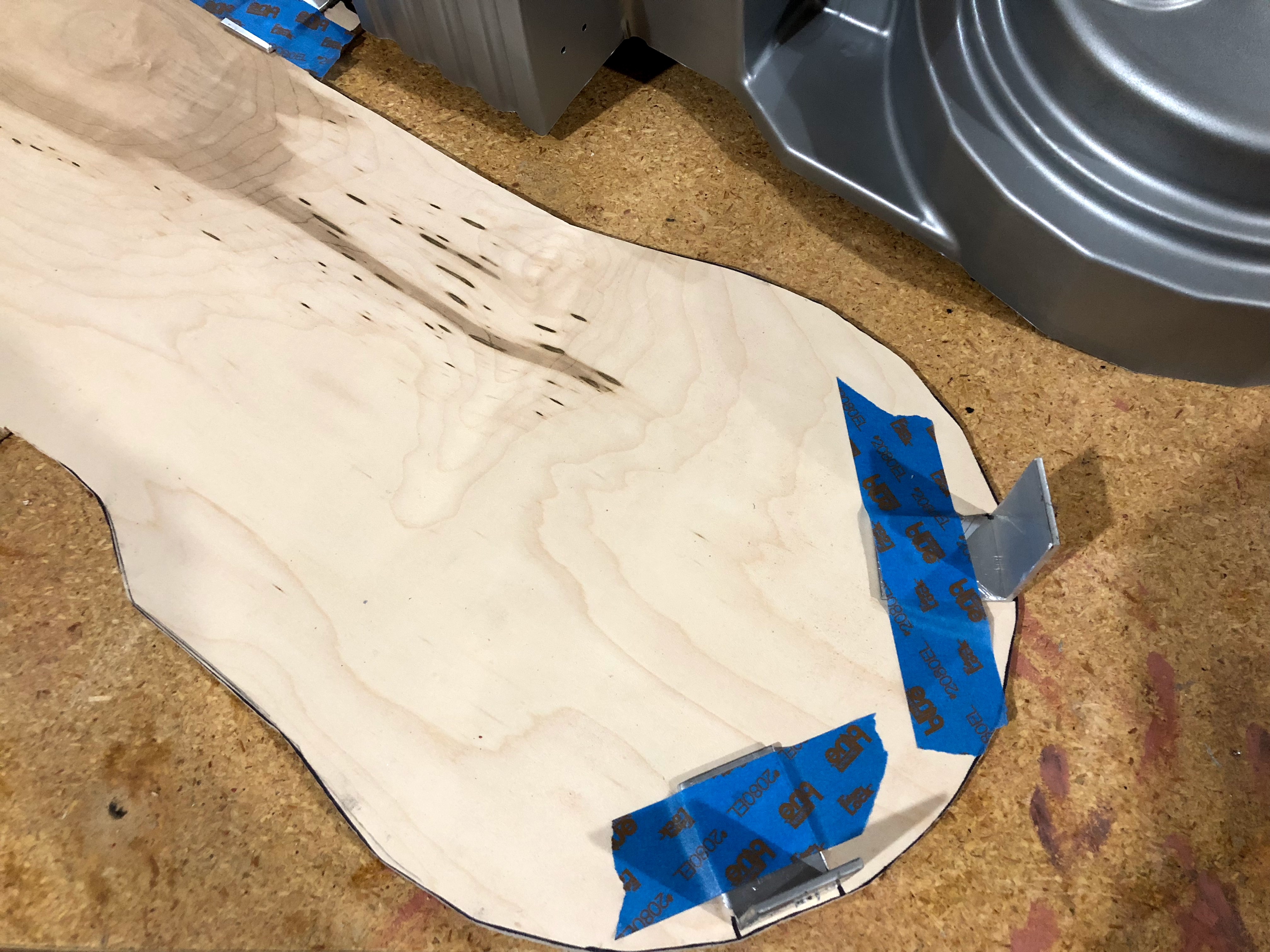
The blank brackets taped in place for test fittings.
The only issue was my original brackets had offset holes, so the holes in the shell weren’t in a straight line. That isn’t screen accurate. I looked for more reference images and determined just one screw was the way to go. One screw is accurate (I think) at all four points and easier to take off to remove the shell. The “extra” holes on the bottom would be covered by the cosmetic plating (the plates aren’t part of my shell), so no one will ever have to know about them. Once it all looked good, I detached the shell and set the motherboard aside for painting with the shell.
Note: The first holes I drilled were not screen accurate. The plates hid the incorrect holes at the bottom, but I still had holes at the top of the pack. While picking up paint at the local hobby store, I saw a plastic welding kit called Bondic (https://www.amazon.com/Bondic-Anything-Waterproof-Resistant-Plastic/dp/B00QU5M4MG – it was just $11 at my local shop). It’s liquid plastic that cures when exposed to UV light. It’s meant for making repairs to plastic and my shell and 3D prints are plastic. I thought maybe it could patch the holes and help repair 3D prints, so I bought it to try it out. It actually worked shockingly well. The plastic is really viscous so I was able to apply layers on top of the thin plastic of the shell, fill the holes, and flash the plastic with UV light to harden it. Then I just smoothed it to the outer surface with an X-Acto knife. A black Sharpie was sufficient to mask the patch job and showed me it would take paint well. I used this to patch the incorrect holes so I could drill screen-accurate holes.
Reinforcing The Shell
The shell is sturdy and really only bends when on its own, i.e. unattached from the motherboard. It will spend most of its life attached to and reinforced by the motherboard. However, I reinforced some parts of the shell with fiberglass.
Once attached to the motherboard, I pushed on the edges of the shell and found some parts would twist or bend, primarily the power cell. I used the same mounting points for the four aluminum brackets that the real Ghostbusters hero packs used, but my plastic shell could have used more to keep everything rigid. That would have required more screws (making it a less accurate replica) and made it more difficult to remove the shell anytime I wanted to adjust the electronics. I opted to pick-up some fiberglass resin and cloth / mat to stiffen these areas. This would provide some rigidity.
I used fiberglass mat for this. The areas I reinforced had gentle curves and flat spaces and I wanted strength. The mat worked for this. I also cut some fiberglass cloth for a few other areas I thought could maybe use some additional strength in case of accidents. I was already mixing up fiberglass, so I figured why not. After it cured for a few hours, I was unimpressed with the reinforcement. Everything still had some flex. The next day, though, I noticed the areas with fiberglass had lost a lot of their flexibility. The shell was now sturdy against the motherboard. The cold temperatures of my basement may have prevented the fiberglass from curing to full strength in one evening.
Painting The Shell
With the shell reinforced, the holes drilled, and the motherboard prepped, there wasn’t anything stopping me from painting these items. I already sanded the shell to help the paint bite into it, so I applied the primer. While that dried, I sanded the motherboard, wiped it down, and applied primer. I really only bothered hitting the edges and the back. I left the “inside” unpainted to allow me to mark it up when planning the electronics.
I painted the motherboard with metallic spray paint. It’s a thin piece that will be mostly hidden by the ALICE frame and the pack itself, but reference images show the motherboard has some weathering. You can see the bare aluminum in places along the edge where the motherboard’s paint was scratched or chipped and this weathering doesn’t line up with any damage on the pack. I thought weathering the motherboard would be a nice touch. I applied a little masking fluid on the edges and then painted it flat black.
I gave the shell a few coats of metallic spray paint. I did several light coats to let the glossier metallic finish paint would really cover the flat grey primer. I could have bought a can of glossy primer to help, but I already had several cans of flat primer. The vast majority of the surface area will end up covered in flat black anyway. This coat is mostly for accenting and the reference images show a lot of the pack’s weathering looks very dull and grungy, not shiny and metallic. As with the other pieces, I applied a top coat to protect the metallic coat before continuing.
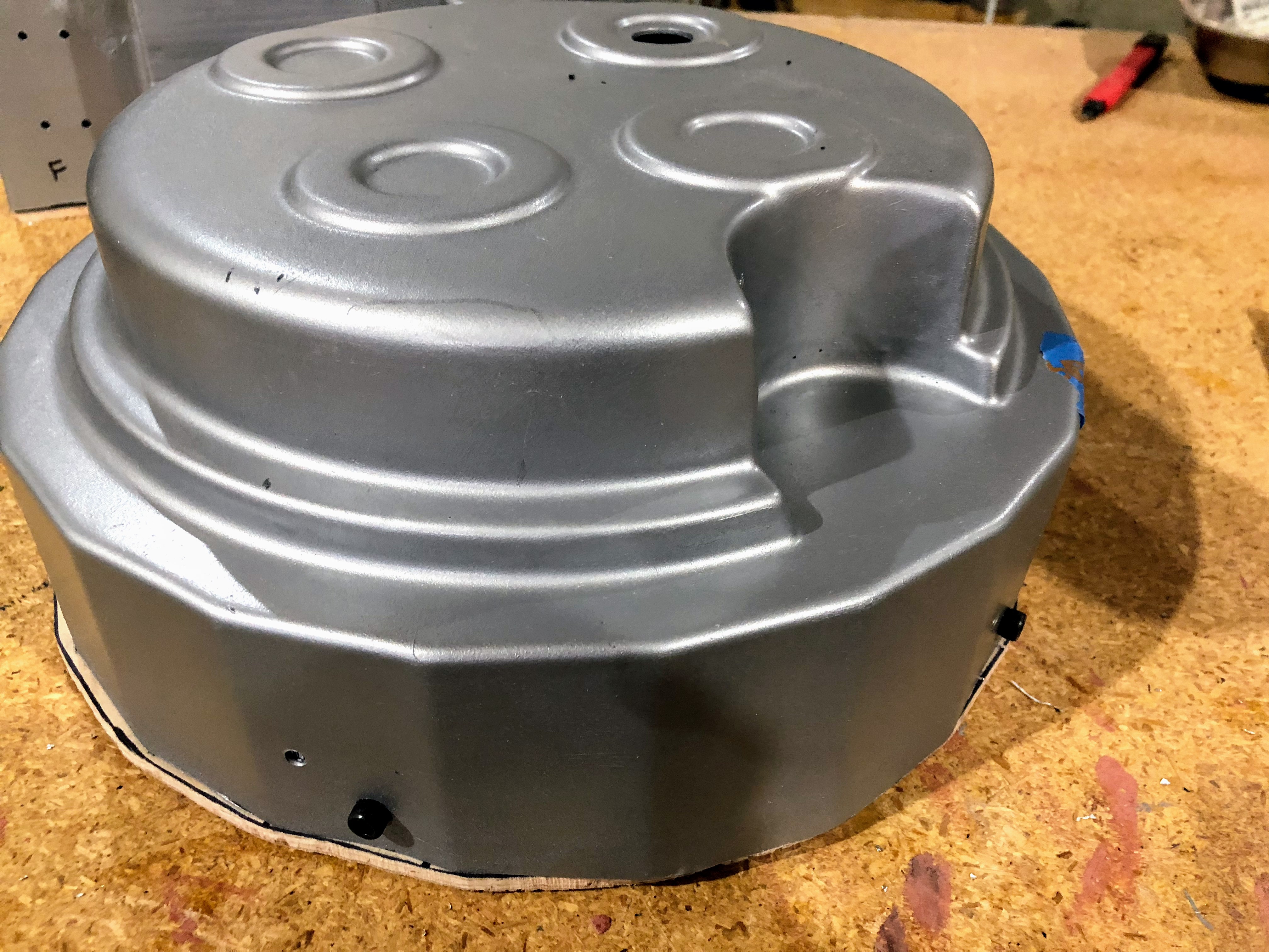
Here is the shell with the first coat of metallic paint, test fit to the motherboard which still needed trimming. Also, you can see where I started drilling a hole for the lights before realizing my biggest step bit was too small for these holes.
I then started the weathering process with my latex masking fluid. I used images of the Anovos “Spengler” pack as a guide, but also did my own thing. The big scuff on the cyclotron is inspired by the Spengler hero pack as pictured on Anovos’ site. This part was a lot of fun and I really enjoyed painting it. Finally, I painted the shell flat black and removed the latex mask.
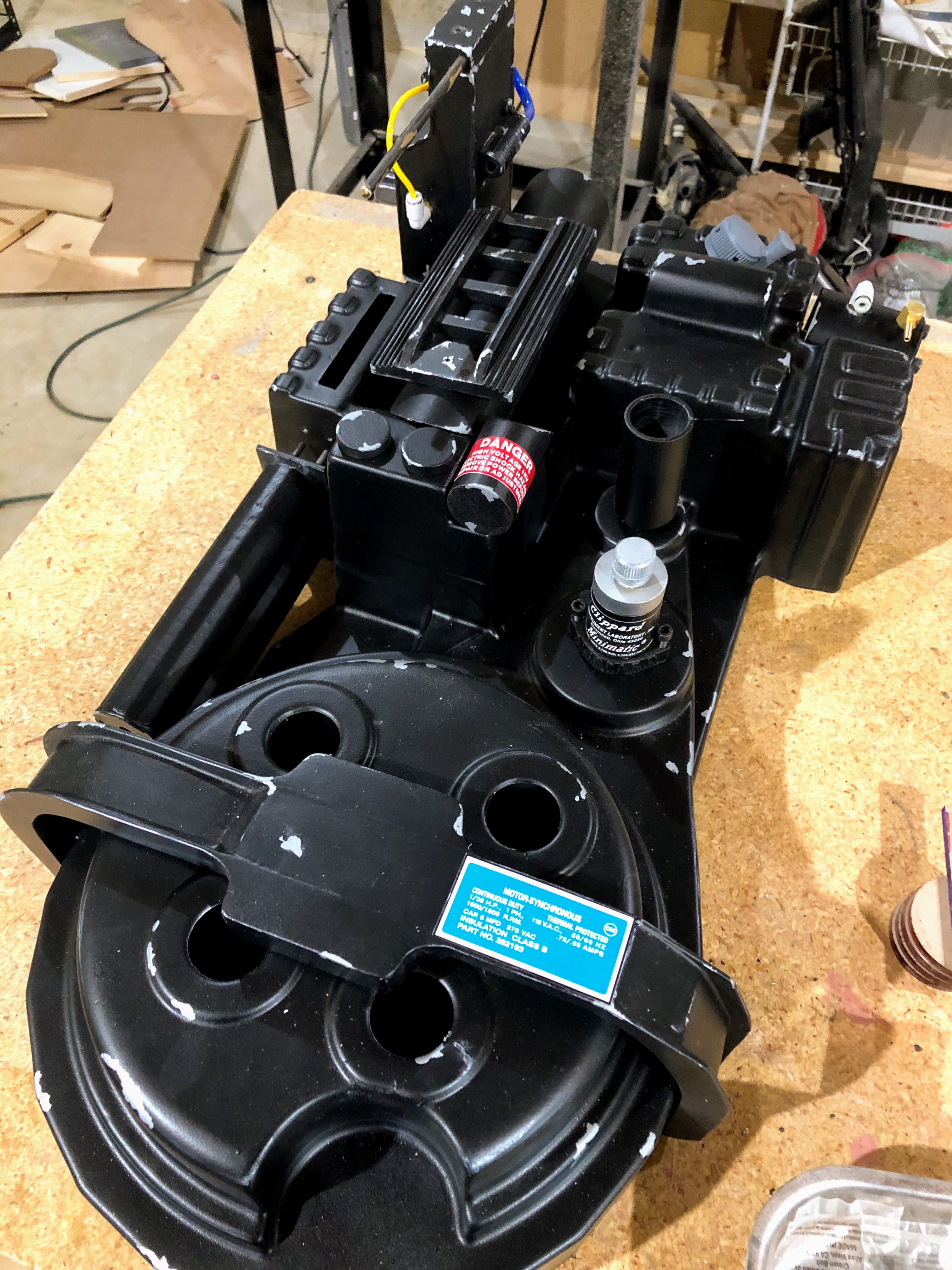
The weathered shell and a few pieces laid out to get a look at my progress.
Making The Bumper
The pack was looking good, but no pack is complete without the bumper and shock mount. Crafting a bumper is maybe the biggest task, at least in a pack like mine. It needs to be sized properly for the pack, it has a deceptively complex shape with curves and changes in thickness and angles. I explored 3D printing this piece, but ultimately decided that was a bad idea. The biggest issue is its size. I’d have to print it in pieces. Then, due to the overhangs and changes in thickness, I’d have to cut the pieces into pieces. At a minimum, the bumper would be split into two sides and a middle piece and then the side pieces would be cut in half lengthwise for easier printing. Then there’s gluing it all together. I would have a perfectly sized pack, but assembly seemed like it would be a nightmare. A secondary concern was durability. I anticipated this piece being the most likely to take the brunt of a collision or drop and wanted it to be durable and to offer some level of protection for the lower pack. It is the bumper after all.
A lot of the builds I reviewed while preparing for this seemed to use resin casts. They are available for $60 on gbfans.com, but that’s a pricey replica and I wanted to make mine. I did a lot of reading on how to build one of these. One of the best looking bumpers I found included a set of templates. They were shared by ThePinkGhostbuster on gbfans.com, here:
http://www.gbfans.com/forum/viewtopic.php?t=10169
The bad news was/is the referenced website no longer exists. This is mentioned in the thread, but that disappearance was temporary in 2012. That temporary outage worked for me in 2018. With ThePinkGhostbuster’s site down, gbfans.com hosted the files for everyone and never removed them, so I was able to download the PDFs.
On a side note, I was able to track down the creators and I believe they went on to form Atomic Tiki Studios (https://www.facebook.com/AtomicTikiStudios/). They don’t have a website, but their Facebook page is active and, as of this writing, is currently showcasing the latest updates to their The Real Ghostbusters proton pack “Mark II” builds. ThePinkGhostbuster also has old threads walking through the creation of their first RGB packs, presumably the “Mark I.” It looks like ThePinkGhostbuster and company only have a presence on Facebook, but the pictures suggest they really expanded their operations by adding a CNC machine and other equipment. Very cool stuff.
I did find the old site on the Wayback Machine. While the thread makes it sound like the site had additional instructions for the bumper, the site seems to have just hosted the PDFs. The only instructions were/are on the PDF plans. Luckily, construction is easy enough. I had the plans printed on 11x17 paper for $0.60.
The plans call for MDF in three sizes, but I could not find 1/8” MDF. I substituted 1/8” tempered hardboard, the sort you usually use as backing for shelves or cabinets. I found project sized boards in 1/4” and 1/2” MDF boards (4x4) at Home Depot. Everywhere else I looked only had 3/4” or 1” in huge sheets. With my boards in hand, I cut out the templates with an X-Acto knife and traced them onto the boards in pencil and marker. Then I cut them out on my band saw.
Everything had to be assembled in pieces to avoid issues with sanding. I don’t have a CNC machine or a laser, so my cuts were never going to be perfect and each piece was slightly different. I glued the three center pieces together first and clamped them. I let them sit overnight to escape my workshop that was now covered in MDF dust. The next day I used an orbital sander with 80 grit paper, 150-grit sandpaper, and a Dremel with a sanding bit to even everything out and level all the surfaces. I smoothed everything, made sure angles were correct, and then gave everything a light sanding with the 220-grit paper. Finally, I checked the fit over the shell. I did this after sanding because sanding removes material, right? My shell didn’t have its cosmetic plating yet, so the fit was a little lose but looked accurate.
After confirming the fit looked alright, I went to attach the side panels. These are the 1/8” pieces and must be 1/8” for the rest of the pieces to fit and look right. As mentioned, I had substituted tempered hardboard for these and quickly decided I hated it. The surface of the hardboard, especially the back’s fabric-like quality, just looked off. I sanded a scrap piece and painted it flat black as a test and did not like the results. I tried sourcing 1/8” MDF and found it available online, but the cheapest option was $30 for a pack of 12 sheets from Amazon. That would do it, but I decided if I was going to spend another $30 and then have to store 11 sheets of MDF then I might as well buy the resin bumper for $60 and save myself a lot of trouble.
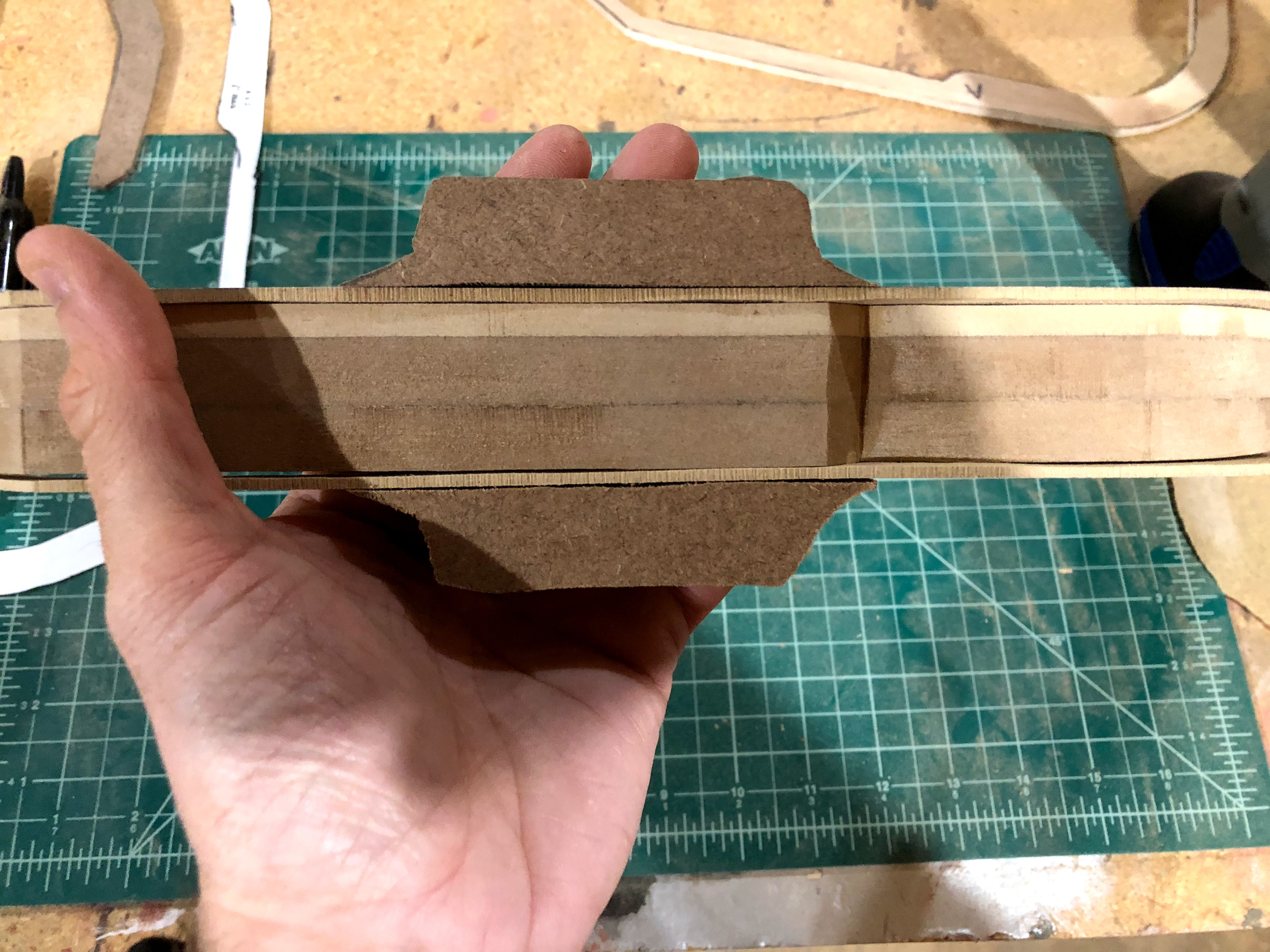
Test fitting the pieces on the glued interior. This thing looks rough!
I was discouraged, but tried something that seemed ridiculous. I cut a new side panel piece from the 1/4” MDF and then cut it in half, the long way. Yes, I cut one 1/4” thick piece into two (roughly) 1/8” thick pieces. It worked surprisingly well thanks to the piece being thing and curved. I very carefully, i.e. very slowly with both hands, fed the end into the saw and used one hand to push and my other hand to pull. After sanding the ragged sides, the fit was perfect and I glued the sides onto the interior piece. The only issue I had was the side panels did not have entirely uniform thickness because I cut them manually. They looked fine, but this meant extra clamping when gluing to make sure there was good contact with the main body.
This led to another round of sanding with the Dremel to smooth everything out. Meanwhile, the B pieces were glued together and clamped. When the sanding was done, I glued and clamped the combined B pieces to the underside of the bumper. I also glued the top C pieces on at this point. Then there was just a lot more sanding. When the edges were smoothed out, I filled in gaps, nicks, and the interior edges with Bondo putty.
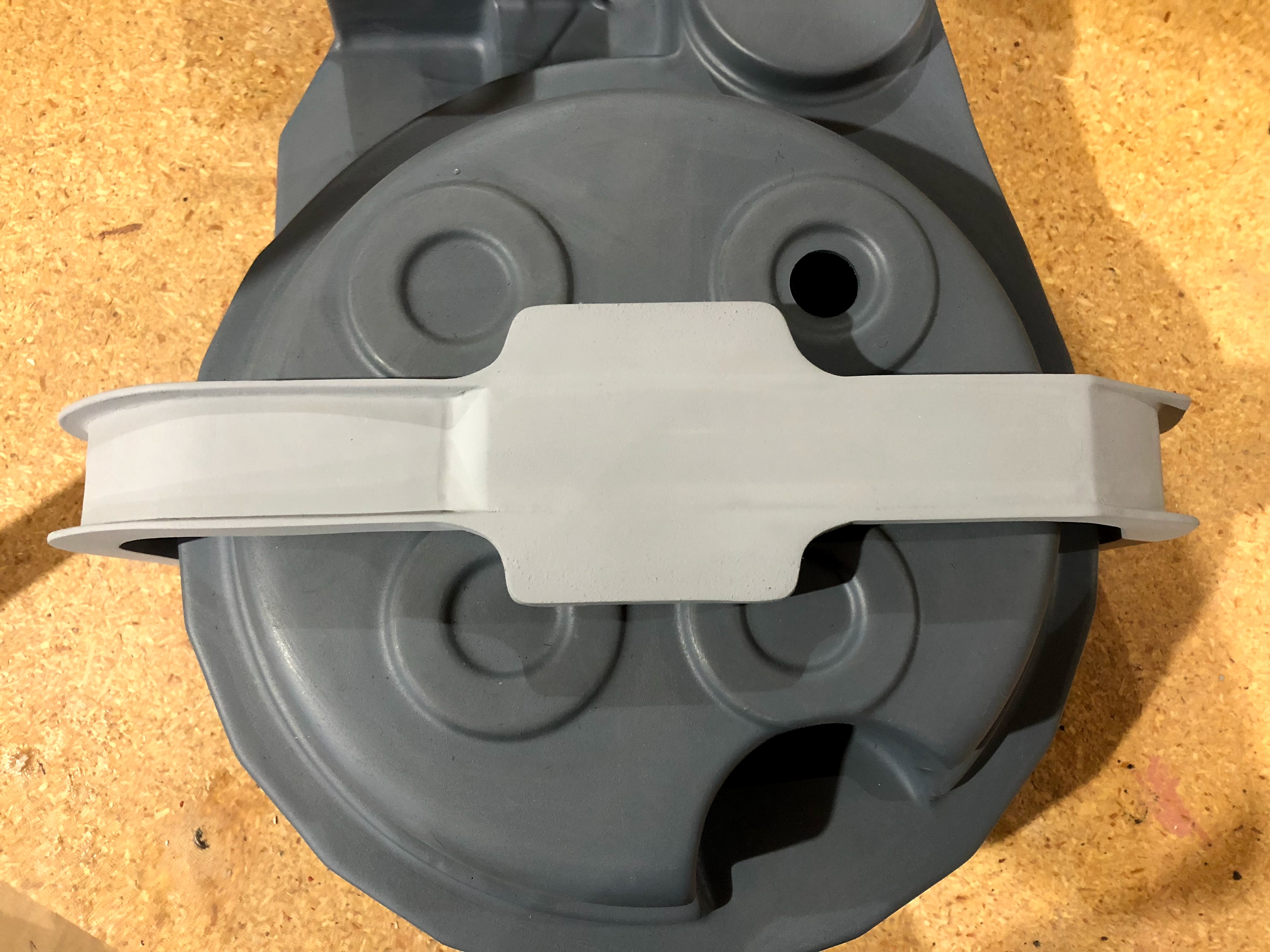
You can’t even tell it is MDF :)
This thing looked like hot garbage at first. Then it improved as I glued and sanded. It turned out far better than I expected it would. This helped sell me on the idea of using MDF for pieces of the gun and for future projects. It’s easy to cut, sands reasonably well, and looks good. However, I don’t think my shop will ever recover from the MDF dust that coated everything within 20 feet of my band saw and work table.
I still could have done a better job with it. The primed bumper looked perfect, but the flat black paint made it easier for me to see some rough areas. It wasn’t the end of the world, though. Most of the rough areas ended up underneath where no one will ever see them. The only major defects were slight lines where the seams were (these were filled, sanded, filled, and primed, but clearly these seams are stubborn) and some nicks on one side. The lines are negligible and I hit the nicks with some rub ‘n buff to make them look like the metal bumper took a hit on the side. It turned a negative into a feature.
Making a Shock Mount
I considered 3D printing the shock mount, but it is such a centerpiece item that I felt it should look really good. I went with the “washer method” that is popular on gbfans.com and made the shock mount out of metal washers. The shock mount alternates between a larger ring and a smaller ring. I used a 4” carriage bolt and four sizes of washers.
The washers and carriage bolt are 5/16”. The shopping list included:
- 12 x 1 1/2” fender washers
- 12 x 1 1/4” fender washers
- 2 x 1 1/2” fender washers (3/8” inner ring)
- 1 x 1 1/4” fender washer (3/8” inner ring)
The three 3/8” washers were for the top. The larger inner diameter allowed the washers to go over the bolt’s squared collar and allow the bolt’s head to sit flush with the washers. I still had to file the collar to round it a bit before the washers slid easily to the top, but the metal was soft and filing was quick and easy. I slid the 3/8” washers on first. These three washers covered the bolt’s collar and then I slid on the rest alternating between 1 1/2” and 1 1/4”. I started and ended with the larger washers, as per Otto’s plans.
According to plans, there should be twelve larger rings on the shock mount and the whole thing should be 42mm tall. I used fourteen and ended up with a little over 40mm (not counting the bolt’s head). The thickness of the washers match the plans, but it’s possible there is some variance or the washers are just off by enough to be noticeable when twelve are stacked together. I liked how fourteen looked and felt in my hand. The height and weight looked right, even if the count is technically off, so I went with it. I secured everything with a nut and rubbed the shock mount with 2000 grit sandpaper.
Attaching The Shock Mount
I measured the bumper to find the center and drilled a 5/16” hole through it. Then I flipped the bumper over and used a forstner bit to make the hole big enough to accept a 5/16” nyloc nut. Before attaching the shock mount, I cut a hole in one of those rubber grippy pads often placed on legs of furniture and stuck it on the end. This was to help add a cushion between the paint job and the metal washers and prevent the shock mount from spinning.
I slid the bolt through the hole in the bumper and threaded the nut. This was kind of tedious and difficult because a ratchet wouldn’t fit into the hole, so at the very end I had to switch to holding the bolt with pliers while using another set of pliers to grip the edge of the nut and turn it. To cap things off, I grabbed a plastic spacer I had lying around and cut it down to about 1/3”. I slid this onto the bolt and placed the bumper on the shell. I checked to the ends of the bumper and whittled away at the plastic spacer until it was about 1/4” and the ends of the bumper rested at the bottom/back of the shell. The bumper does not sit against the cyclotron and the screen-used proton packs used spacers like this.
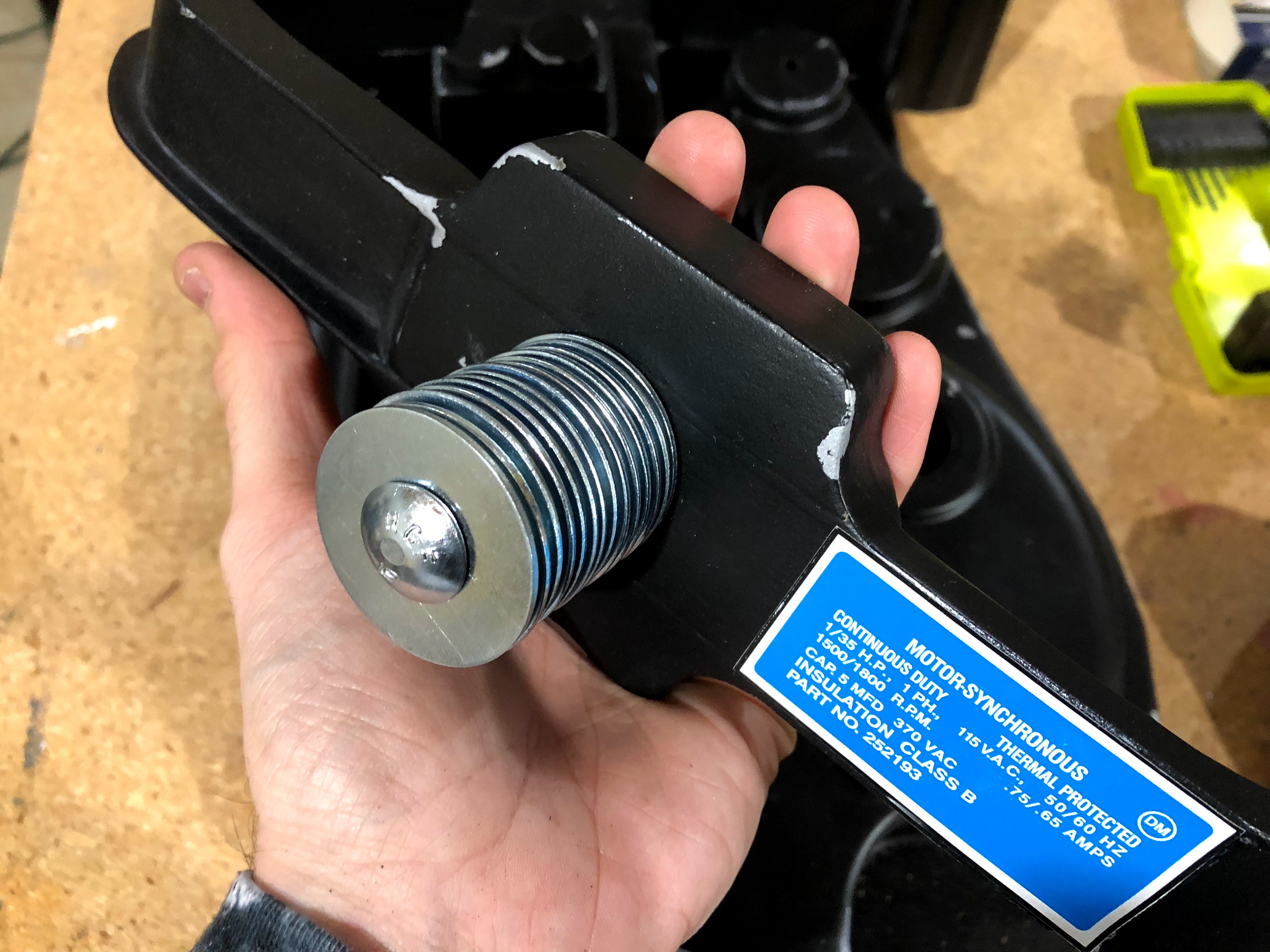
The weight feels perfect, the washers don’t rattle, and it’s nice and shiny.
Assembling The Pack
At this point I had a reinforced, painted, and weathered shell, painted and weathered attachments, and all of my holes drilled. It was time to begin assembly. I gathered up scrap wood and plywood sheets to make anchors and started.
I used plywood, tempered hardboard, and bits of pine to act as buffers between the part being attached and the screw heads. This added stability so parts wouldn’t wobble, but most importantly it made it much more difficult for an accident to cause a screw head to be yanked through the shell.
A mix of plywood and tempered hardboard was used. Carpet tape helped keep the pieces in place while drilling. The following is the order I attached each item to avoid logistical issues.
HGA
I finished my HGA by inserting the Legris elbow, Clippard hex fitting, and M6 socket head screws. I put the label on a 1/4”washer and secured it to the HGA with another M6 screw.
The HGA is just a cylinder, so there’s not much else to assemble. Tgoacher came up with a nice solution for attaching it to the pack. A smaller cylinder insert fits snugly inside of the HGA and holds a bolt. I applied some super glue to the bolt before I slid it all of the way through my insert. Then I did the same thing with the insert and the HGA. The bolt was inserted into a pre-drilled hole in the shell, passed through plywood, and secured with a wing nut.
Acrylic Color Plates I used rubber cement inside of the pack to attach the acrylic pieces for the cyclotron’s red lights and the power cell’s blue light strip. These looked nice as is, but will look fantastic once lights are installed. I did this now because some of the bolts and wood supports for pieces like the Ion Arm and N-Filter cover or obscure the acrylic plates just enough that it would be annoying trying to glue them in place later. I just left the paper on the back to avoid the plates getting scratched or dirty while I was attaching everything else.
PPD
This could have been easily glued into place, but I didn’t want to attach too much to my shell permanently or have the glue fail on an exterior piece like this. Instead, I used two #4 wood screws to secure it in place. This way I could adjust orientation or placement if I got it wrong or needed/wanted to replace the PPD.
Booster Tube, Rounds, and Frame I carefully placed the tube against the angle on the attenuator and looked for any gaps. Once I was convinced I had the tube placed in the proper orientation, I placed some thin strips of carpet tape on the bottom of the tube and carefully aligned everything again. The carpet tape held the tube in place really well. I added some painter’s tape over the top to prevent it from rolling. I used carpet tape on the inside to hold some tempered hardwood in place behind the tube. Then I slowly drilled small holes through the hardwood and shell. I used #4 screws to secure the tube and removed the tape.
I noticed that when the top of the tube is screwed it the bottom lifts just enough off of the attenuator that a gap becomes noticeable. I had some small rubber washers available, so I took two of them, placed them over the top screw hole, and reattached the tube. These washers acted as the perfect spacer. I was able to tighten all the screws and keep the tube in place. The fact that the tube does not sit flat against the shell is unnoticeable.
The booster frame is screwed into the tube, so that’s what I did.
Next, I cut some circles of carpet tape and used them to attach the booster rounds.
Finally, I attached the frame with the ribbon cable collar. I could not find any measurements for the frame placement, so I reviewed a bunch of photos of this area of the screen-used packs and determined the reference photos and Stefan Otto’s proton pack sketch agree the frame sits low on the tube. The bottom of the frame overlaps the PPD and is about even with the bottom of the power cell. Put another way, it’s much closer to the attenuator and booster rounds than the Ion Arm.
The frame attaches using #10 socket head screws and washers, so I needed to drill larger holes here. Seeing as these holes would be seen, I was very careful while wishing I had drilled these earlier. Everything was fine, though. I set the shell on a level surface and placed the frame. I moved it until it laid level without my assistance and was in the right place on the tube. Then I drilled a 1/8” hole. I slowly increased my drill bit size until I had cut a large enough hole to thread the #10 screw. This progression prevented the drilling from damaging the 3D printed surface of the tube. A messy hole would be hidden by the frame, but any major issues might extend beyond the frame.
Now that one end was attached, I realigned the frame and repeated the same process at the other end.
Injector Tubes
The Injector Tubes were attached to the power cell box using four bolts. I pre-drilled the holes using the Injector Tubes’ base as a template and then assembled the whole thing for finishing work. That included using epoxy for weld lines where the tubes met the base and at the bottom of the tubes. Like everything else, the bolts passed through the shell and some plywood to be secured with nuts.
Vacuum Tube
And so began attaching things that stick out from the pack. The vacuum tube is a very basic piece. I made it out of 1” PVC pipe. A 1” OD pipe is slightly wider than the vacuum tube should be, but only by 2mm. It’s not noticeable and doesn’t cause any issues for the shell, so I rolled with it. I used my PVC end cap designs and put a bolt through the hole in the bottom cap and slid it through the shell and a circular piece of plywood. I secured it using a washer and nyloc nut.
Ion Arm
The assembly of the Ion Arm is covered above, but I finished it with a few extra touches. First, I bought a brass sink rod for a toilet from the plumbing section at Home Depot for $2.50. I cut it into two pieces that were the right size for the Ion Arm’s rods and glued them into the top. I then thought it needed a little extra something. That turned out to be hot glue.
The PH25 resistor has a brass nut around the bottom. On some screen-used packs, you can see the PH25 resistor is sticking out from the inside and there is clearly epoxy around the resistor holding it in place. I took a hot glue gun and very carefully made a small bead of glue around the resistor to give my Ion Arm the same look. It a nice touch.
For attachment, I used #4 wood screws to go up through the shell and bite into the Ion Arm model. I added a plywood rectangle between the shell and the screws to help reinforce the attachment. This was done to prevent overtightened screws from potentially ripping through the shell if the Ion Arm ever got caught on something and was yanked. There’s a good chance of that happening one day with it protruding out from the pack with brass rods attached.
N-Filter
I finished my N-Filter by inserting a ring of fine metal mesh backed with some wax paper into the part. I took the mesh from a cheap metal strainer ($4 at Target) and added the wax paper to allow light to pass through while making it so you couldn’t see inside the part. I used 3M spray adhesive on the wax paper to stick it to the mesh. Then I sprayed the inside of the filter. I rolled up the mesh and inserted it into the filter. I made sure to line it up so the two ends of the mesh met between two of the filter’s holes to hide the seam. The spray adhesive and friction kept everything in place while I made adjustments. I added some hot glue along the bottom of the mesh for good measure, just to prevent any slippage.
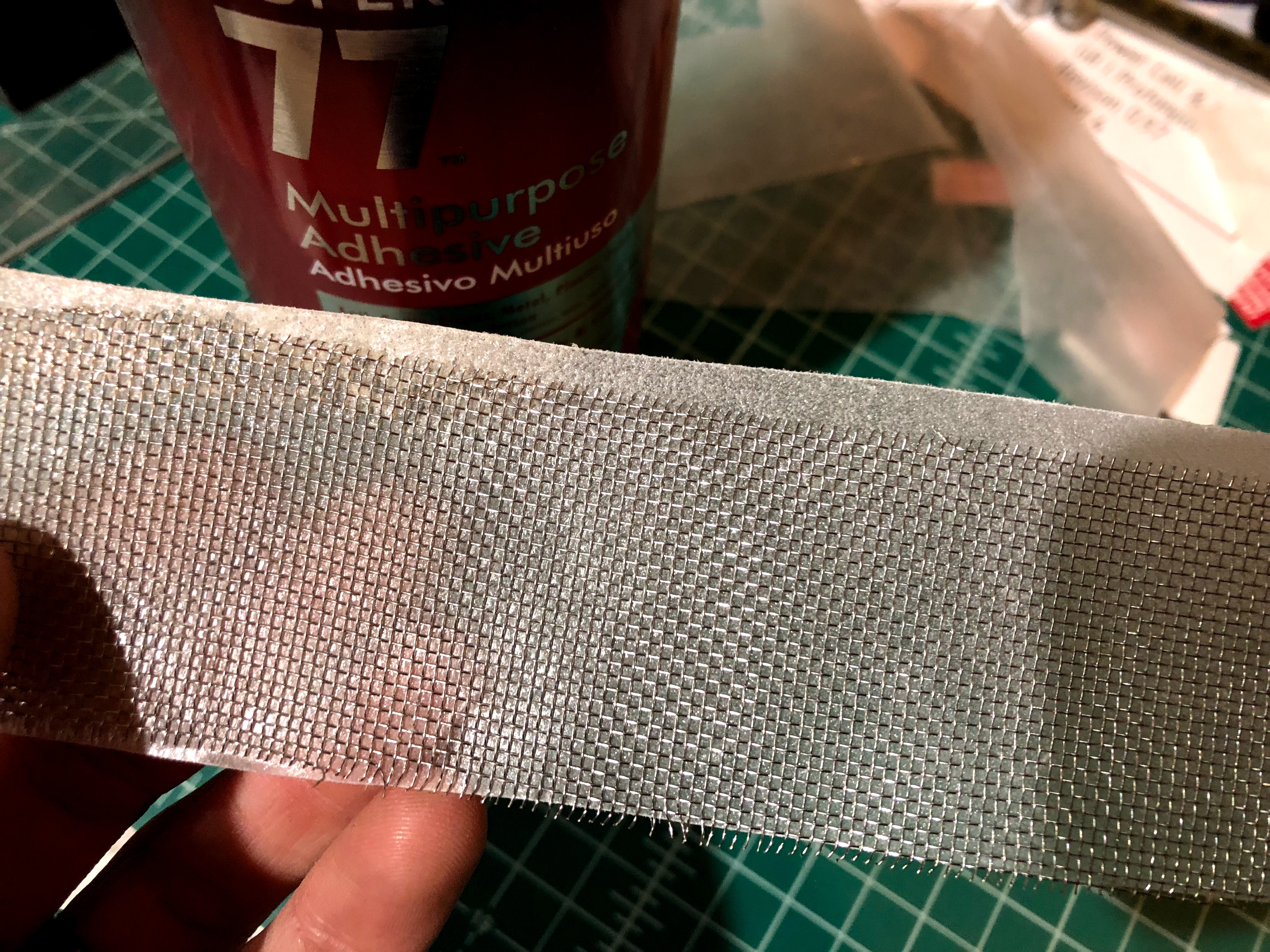
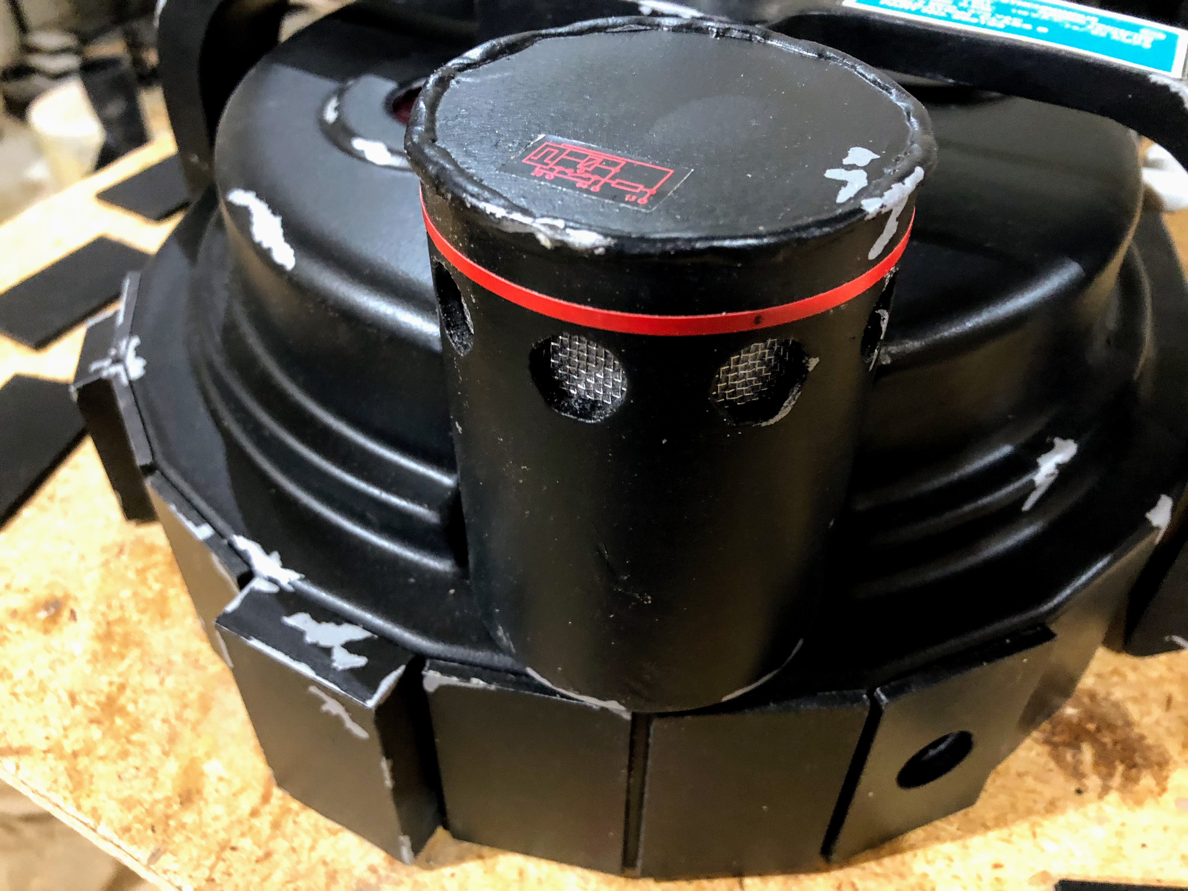
It didn’t have to be pretty as long as it looked nice and neat through the holes. I measured the circumference of the N-Filter and cut a piece of 12mm red electrical tape to the right length. I stuck this to my cutting mat and used an X-Acto knife and a straight edge to cut a 3mm strip. My mat has 3mm marking that were very convenient for this. I then wrapped this pinstripe around the filter. I couldn’t find any measurements showing how far down the pinstripe is. Otto’s plans show the pinstripe is much closer to the the holes than the top, so I used my best judgement and placed it about 1mm above the holes. I think it’s pretty darn close to the real thing.
I attached the filter to the pack using #4 wood screws. I used two from below and one from the side to prevent it from getting pulled down and away from the pack.
Cosmetic Plating
In plans I have seen, “cosmetic plating” refers to the space between the cyclotron and the top of the pack. There are a couple of tubes that stick up out of it and that’s all there is to it. There is also the plating along the bottom of the pack
For the tubes, I used 1” ID PVC pipe. These weren’t 3D printed because when I did print them they became the tubes I mentioned earlier that printed like spider webs. I didn’t feel like printing them again and and properly sized PVC was readily available. I designed and printed my PVC end caps and cut two tubes to the proper length (minus 0.25” added by both caps). I printed three of the caps with the 0.375” holes and one cap without the hole. I glued bolts into two of these caps and then glued them into the tubes. I glued the other two caps into place and painted everything. I attached these to the pack using the bolts like most everything else.
I used some 3M spray adhesive to attach the plates along the sides of the pack’s bottom. The adhesive’s dry time allowed me to attach the plates and make adjustments. I attached them in groups of four and five. I sprayed the backs of the plates, waited 30 seconds for them to become tacky, and put them in place. Then I had five minutes to take a good look at them all and nudge them around until I was happy.
Prior to gluing and painting, I numbered each plate from one to fourteen for weathering. I lined up each plate with weathering on the pack to complete the story I was trying to tell with the various scratches and dings.
Bumper And Shock Mount
The bumper was ready to drop into the hole I had drilled into the cyclotron. I just needed to drill and the hole for it to screw into the side of the pack. This sounds difficult, but careful planning made it a quick and easy process. As per the plans, there are two holes on each side of the bumper. The lower hole is 18.3mm from the bottom of the bumper and the top hole is 19mm / 0.75” above the lower hole. Reference photos and the information available on gbfans.com have the screws going through the bumper and passing into the shell between at a corner between the plates.If the bumper is centered properly on the cyclotron, this lines up naturally. At least it did for me.
I started by marking out the holes on one side and drilled the first hole. I placed it on the shell and lined up the corner between two plates with the center of my hole and then clamped the bumper. This held the bumper in place while I moved to the opposite side and checked if the center of that side was still aligned with the corner between two plates. Once I was satisfied the bumper was aligned properly and straight, I kept it clamped and drilled a hole through the shell using the pre-drilled hole in the bumper. I attached the bumper to the shell using a socket head screw, washer (on the outside, like on the screen-used packs), and nut. Then I could remove the clamp and switch sides.
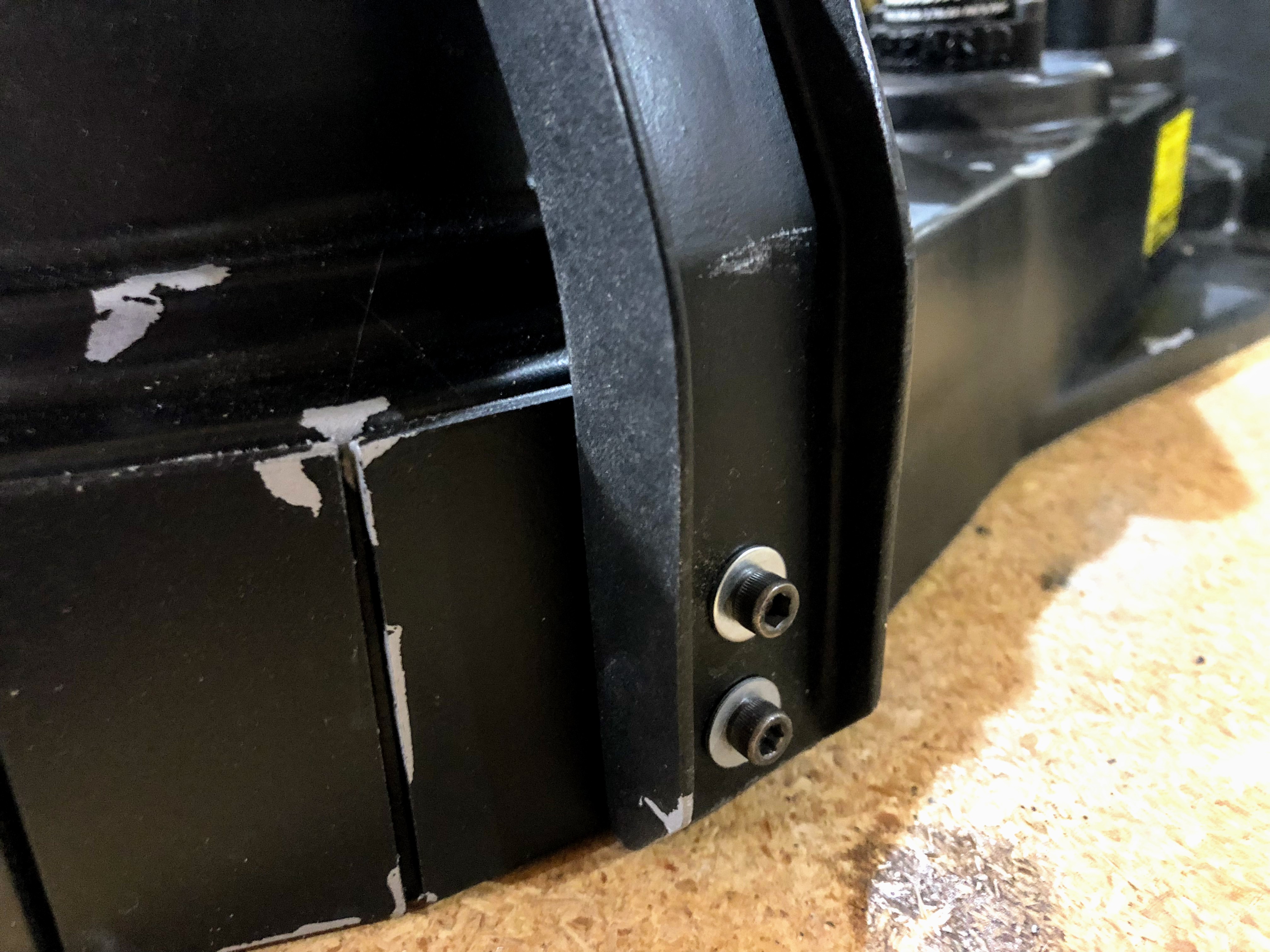
The screws go into the “corner” between the short plate and the next plate on each side.
On the opposite side, I again carefully drilled a hole through the bumper and into the shell. Once done, I inserted the screw to lock that side in place. With both sides now screwed to the shell, I was able to more easily drill the last two holes, one on each side.
Gun Hook
The gun hook was screwed into place on the side of the pack. This piece is meant to have screws you can see on the exterior, so I just cut some plywood to size for the inside of the pack, pre-drilled the holes through the gun hook, and screwed it into place. GGEZ.
This part is also 3D printed, primed, and then sanded using 400 grit sandpaper. I airbrushed it with Aluminum Plate (Buffed), buffed it with a soft rag, and then buffed it with a 2000 grit sanding pad. The result looks like machined metal and has a nice shine to it. Upon close inspection you can see it’s not metal, but that’s pretty good considering it started out as textured black plastic.
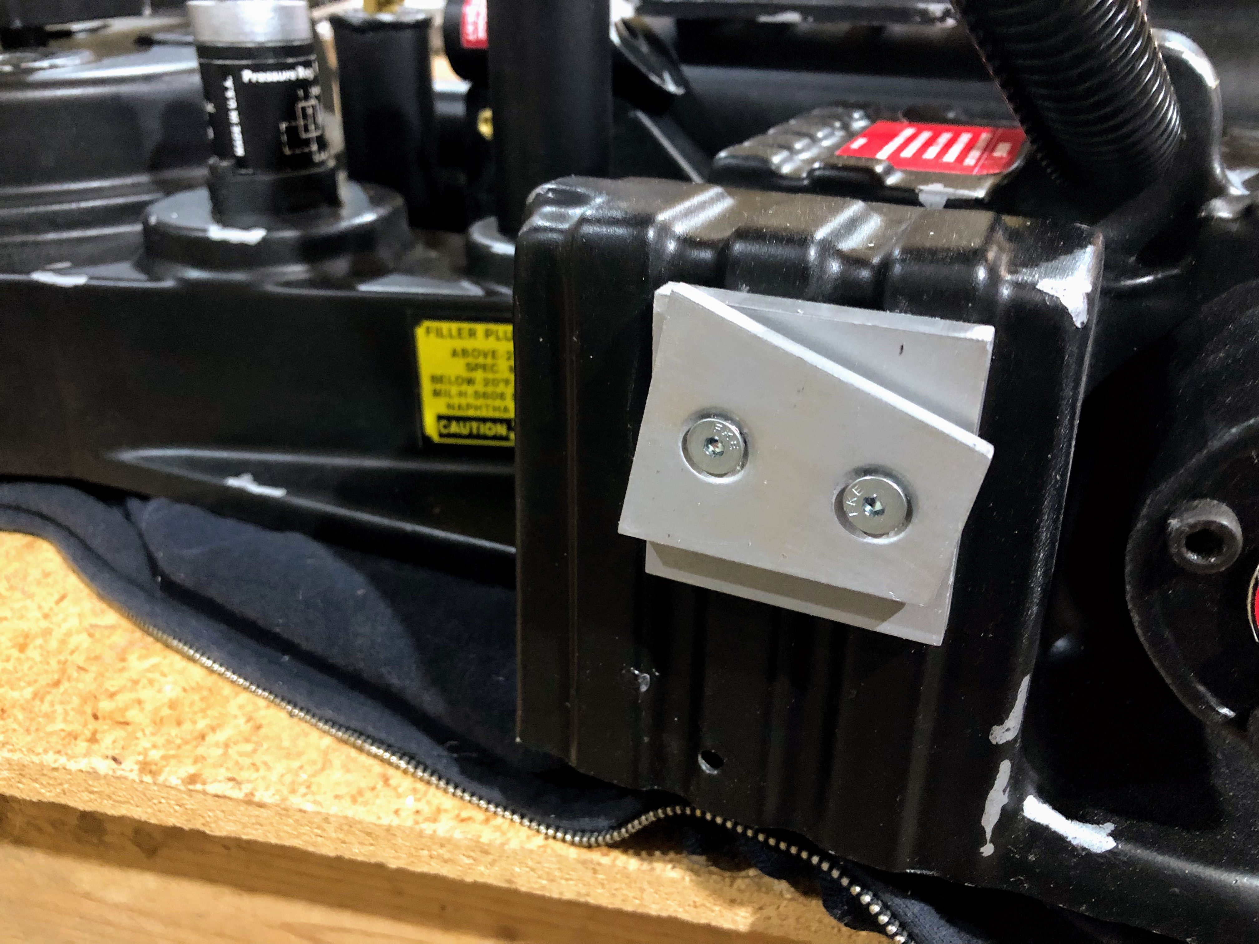
I opted to leave the mounting plate metallic rather than painting it black. It changes from pack to pack and those that are black are often heavily weathered.
The Tubes And Hoses The pack was nearly complete at this point, but a few things remained undone. I needed to attach the ribbon cable and hoses.
I cut the little “boots” for some of the tubes out of 1/4” wire loom and attached the various bits of tubing to the PPD and Clippard / Legris fittings. I used a dab of hot glue to hold the tubing in place anywhere there wasn’t a barb or enough friction to reliably keep the tubing where I put it.
The 3/4” wire loom for the vacuum tube was put into place next. I secured the wire loom using magnet. I cut the wire loom so I would have enough to push it all the way to the bottom of the tube. I glued a neodymium magnet to the end of a dowel, put the dowel inside the wire loom, and used zip ties to keep the dowel inside. The magnet is drawn to the metal bolt at the bottom of the tube and helps keep wire loom from sliding out. Friction handles the rest.
I drilled a 3/4” hole at the top of the pack and didn’t need to do anything else. I twisted the wire loom enough so I could slide it into the hole and then let go. The wire loom expanded back to its original shape and the ribbing keeps it in place.
Ribbon Cable / Spectra Cable
The ribbon cable was the final piece for the pack. I used a Ghostbusters 2 style Spectra cable and real aluminum plates for the clamp. There are a few configurations, but all of them have the cable clamped and screwed to the generator with the screws passing through the ribbon cable. I started by putting my Spectra cable between the clamp pieces and marking the location of the screw holes and the curve of the clamp. I used tin snips to trim the cable to the shape of the clamp and drilled the holes through the cable.
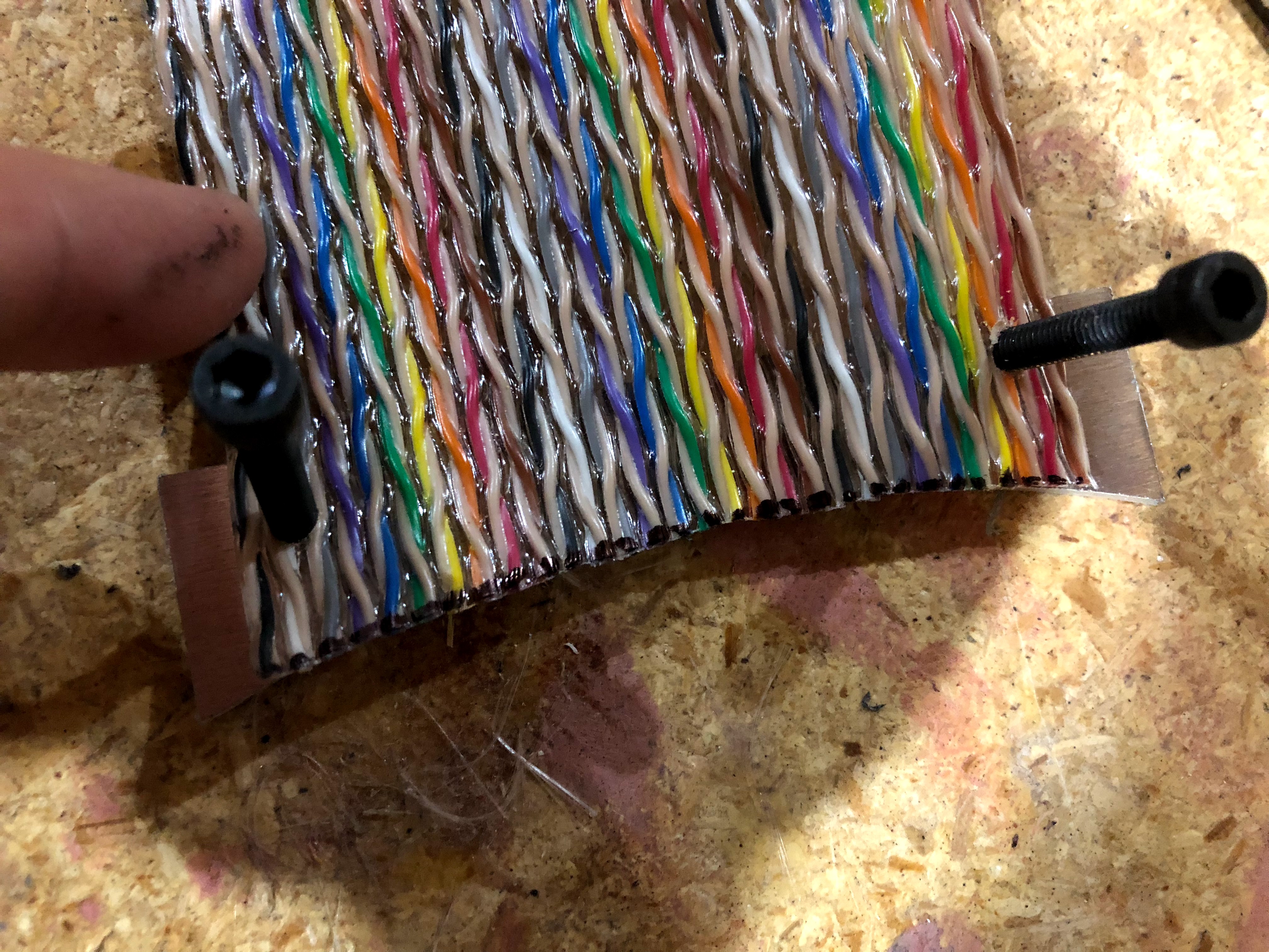
I used a drill on the ribbon cable and snipped the ends to match the curve of the clamp.
I placed the clamp on the generator and drilled my holes. Placement of the clamp is not measured in the plans, so I had to use pictures. Pictures are difficult to judge because the perspective of the camera and slight angle changes make the corner of the clamp appear to point to the edge of the booster tube and attenuator or point to little more to the left. I looked at a lot of reference images and was finally convinced by the close-up shot available on the gbfans.com reference page for the ribbon cables:
http://www.gbfans.com/equipment/proton-pack/ribbon-cable/
The clamp is definitely pointing at the center of the right booster round. If true, that would mean the ribbon cable passes “through” cosmetic plating tube. Indeed, this photo shows the ribbon cable has to bend around the tube. The clamp’s corner points at the booster round and the screw hole ends up being about even with the edge of the far left cosmetic plating tube. This is the positioning I went with.
I twisted the Spectra cable and fed it through the clamp on the booster frame. Using screen grabs of the GB2 proton packs as guidance, I folded the cable over and to the right, passed it through the booster clamp, and the twisted it to fit it through the hole.
I drilled a 1” hole while preparing the shell. This diameter of the hole is not measured in the plans. The only measurement shows the the center of the hole is 3/4” from each side of the corner. I judged a 1” to be big enough for the ribbon cable without being so big that there would be space around the cable in the end. I intend to install lights eventually, so I didn’t want gaps for light to bleed through where there shouldn’t be light. Finally, I secured the extra cable with a zip tie. The fit was tight enough that the ribbon cable wasn’t budging on its own and the zip made a good collar to prevent it from being pulled out.
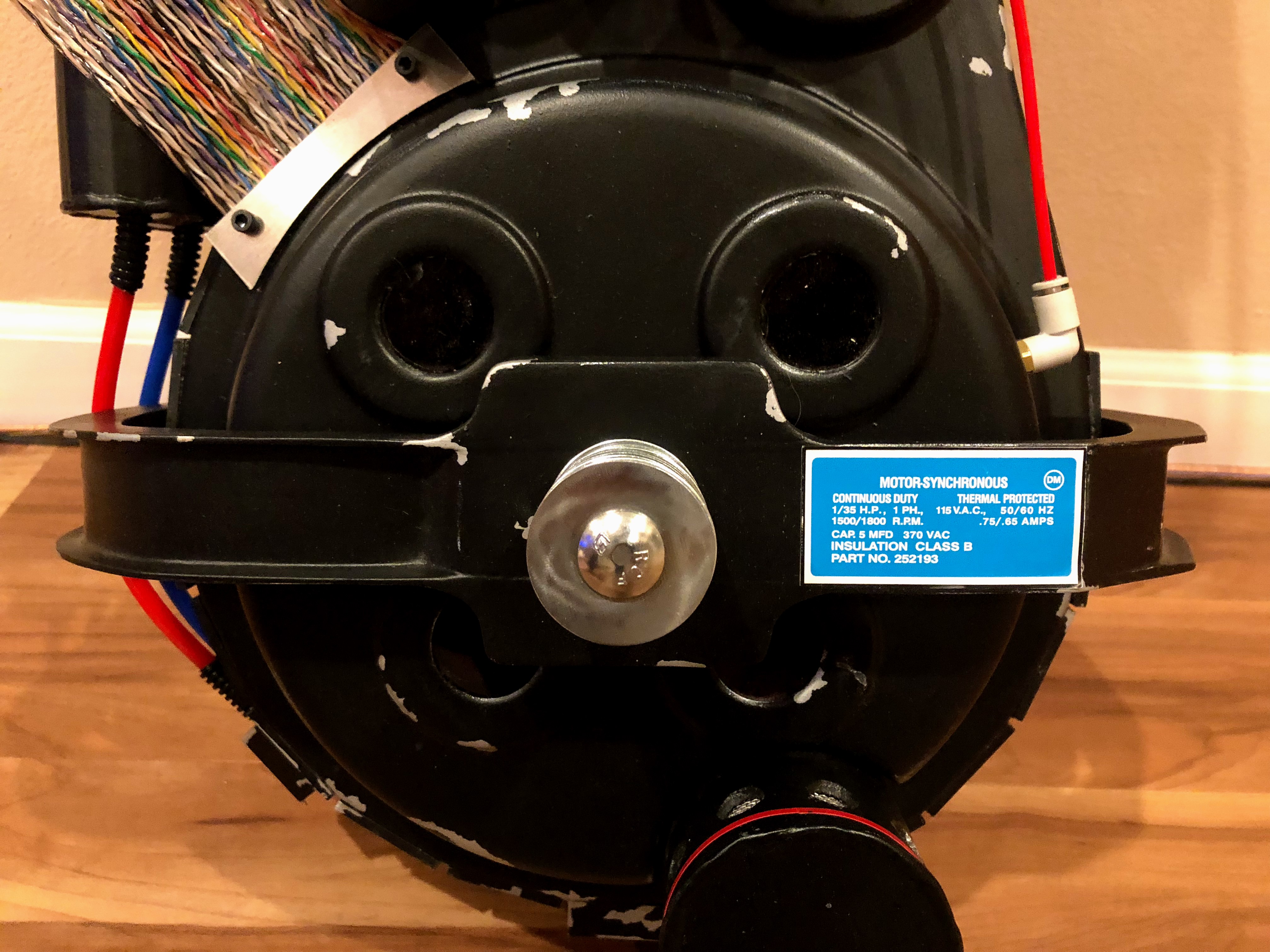
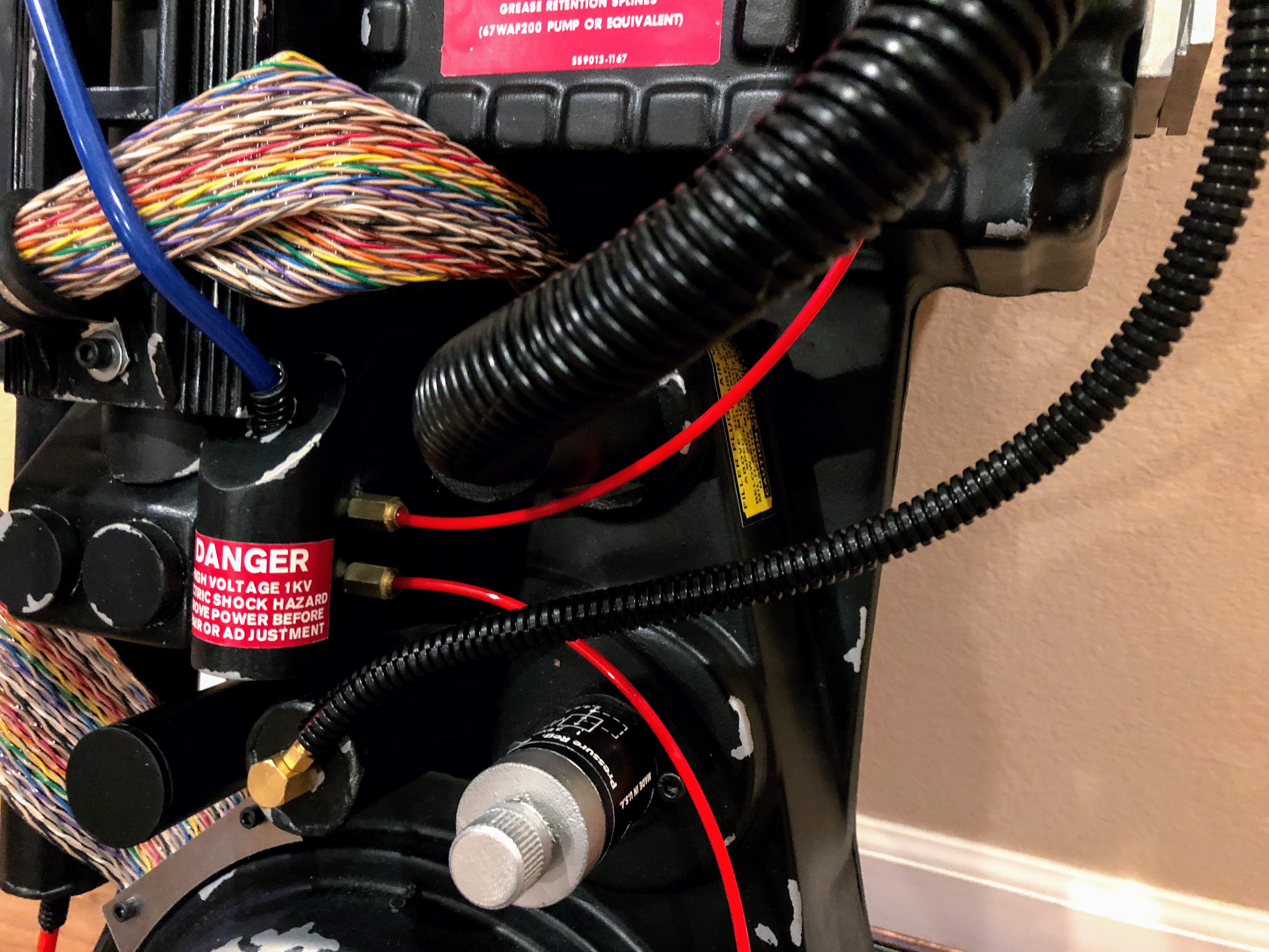
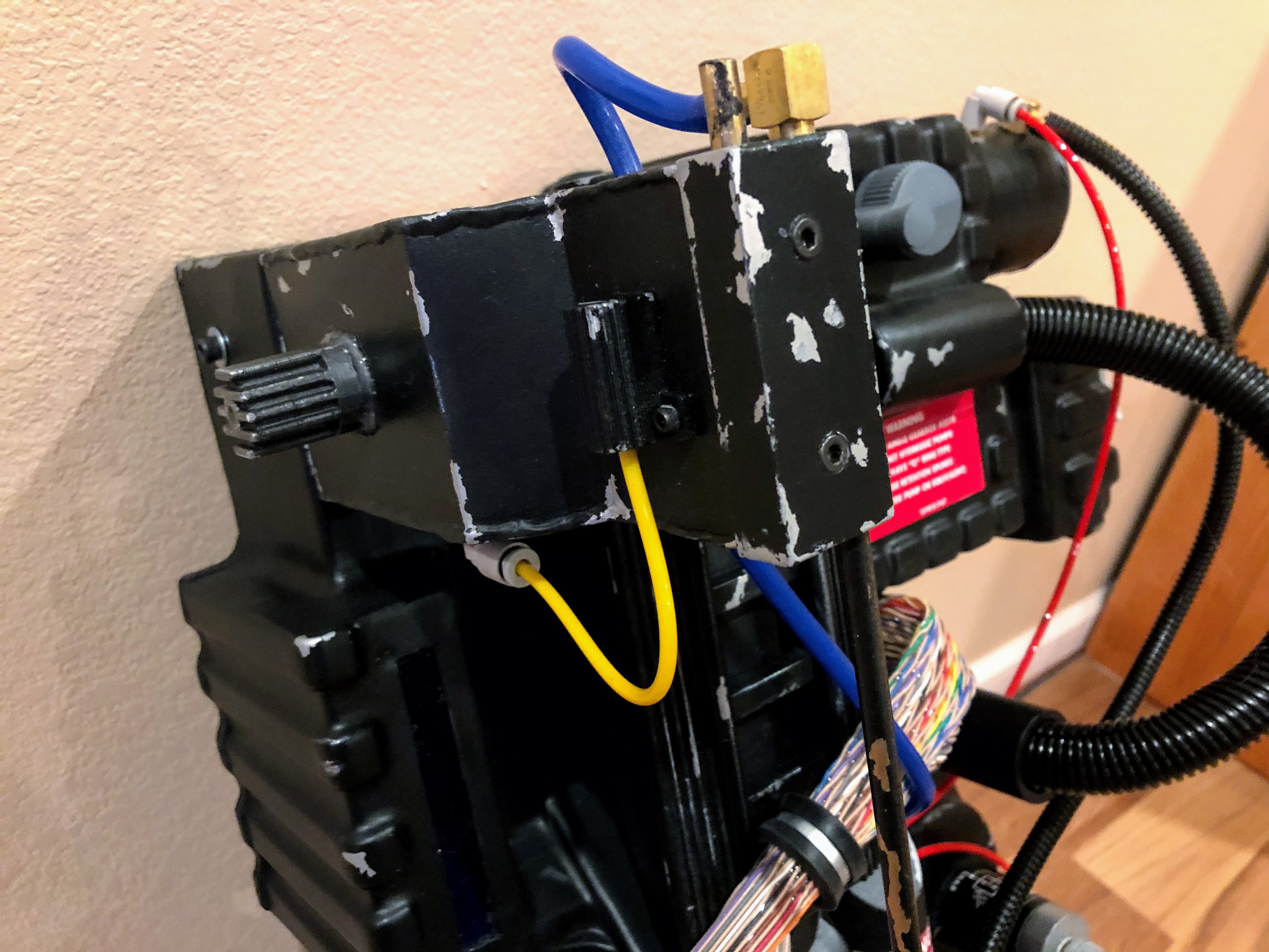
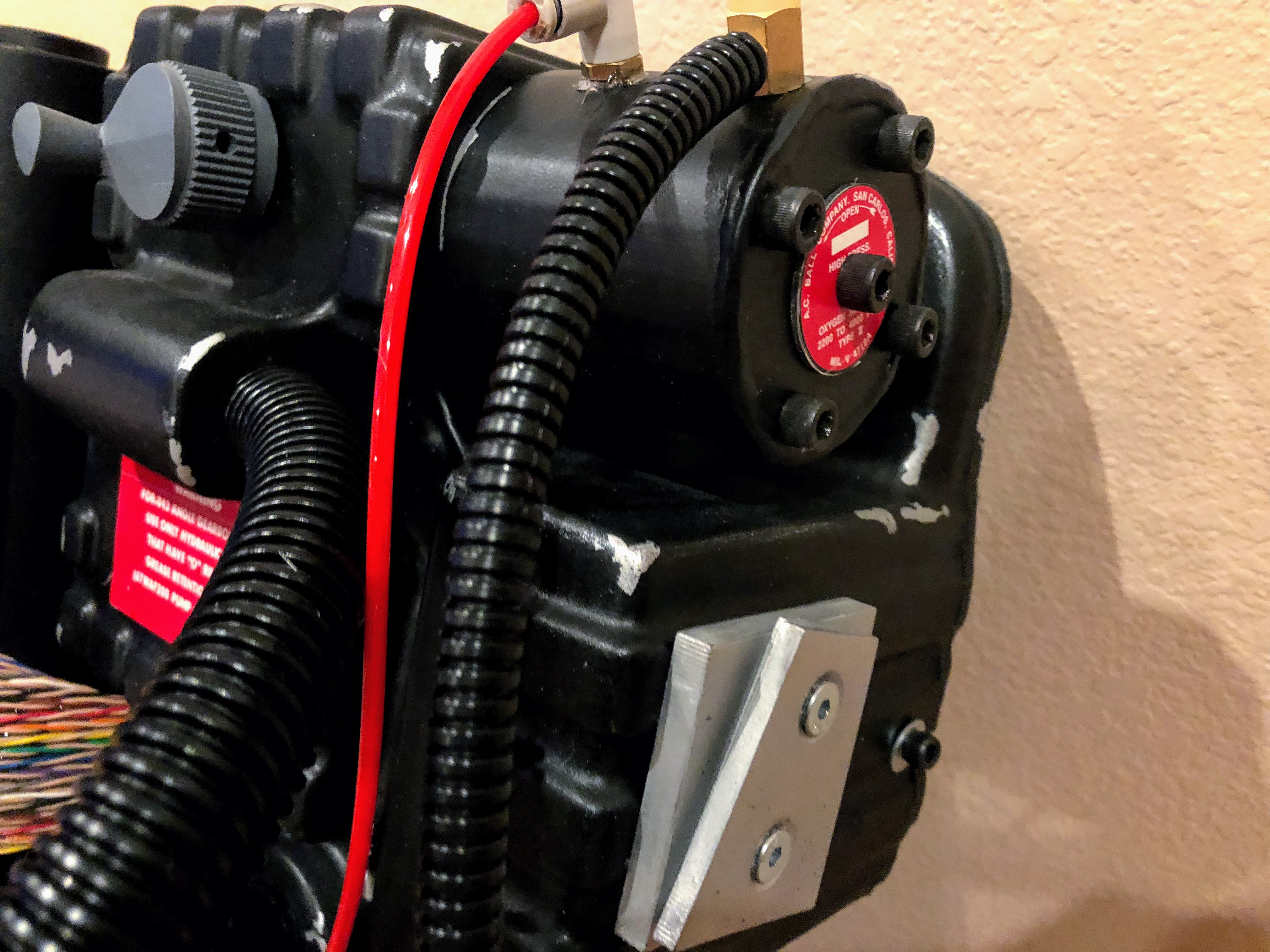
The pack was now 99% complete. The only remaining item was mounting the motherboard to an ALICE frame so I could wear it! A couple of additional items include researching the rest of label placement on some packs (so may add more as I determine what should go where and what I like) and planning the electronics. For now, here is the complete pack. I’ll include more shots at the end.
Final Adjustments
I went back and drilled accurate holes into the gun mount and EDA box. My original holes were close, but not right. I filled in the old holes using Bondic, as mentioned earlier, and marked out new holes with a silver Sharpie. Then I drilled right through the shell into the brackets. I removed the shell and finished drilling through the brackets. While the shell was off, I sanded the Bondic repaired holes and hit the area with some paint. To finish, I put the shell back on the motherboard and tapped the new holes right through the shell.
To be accurate, I used two screws for these mount points.
Final Thoughts
The final pack turned out really well:
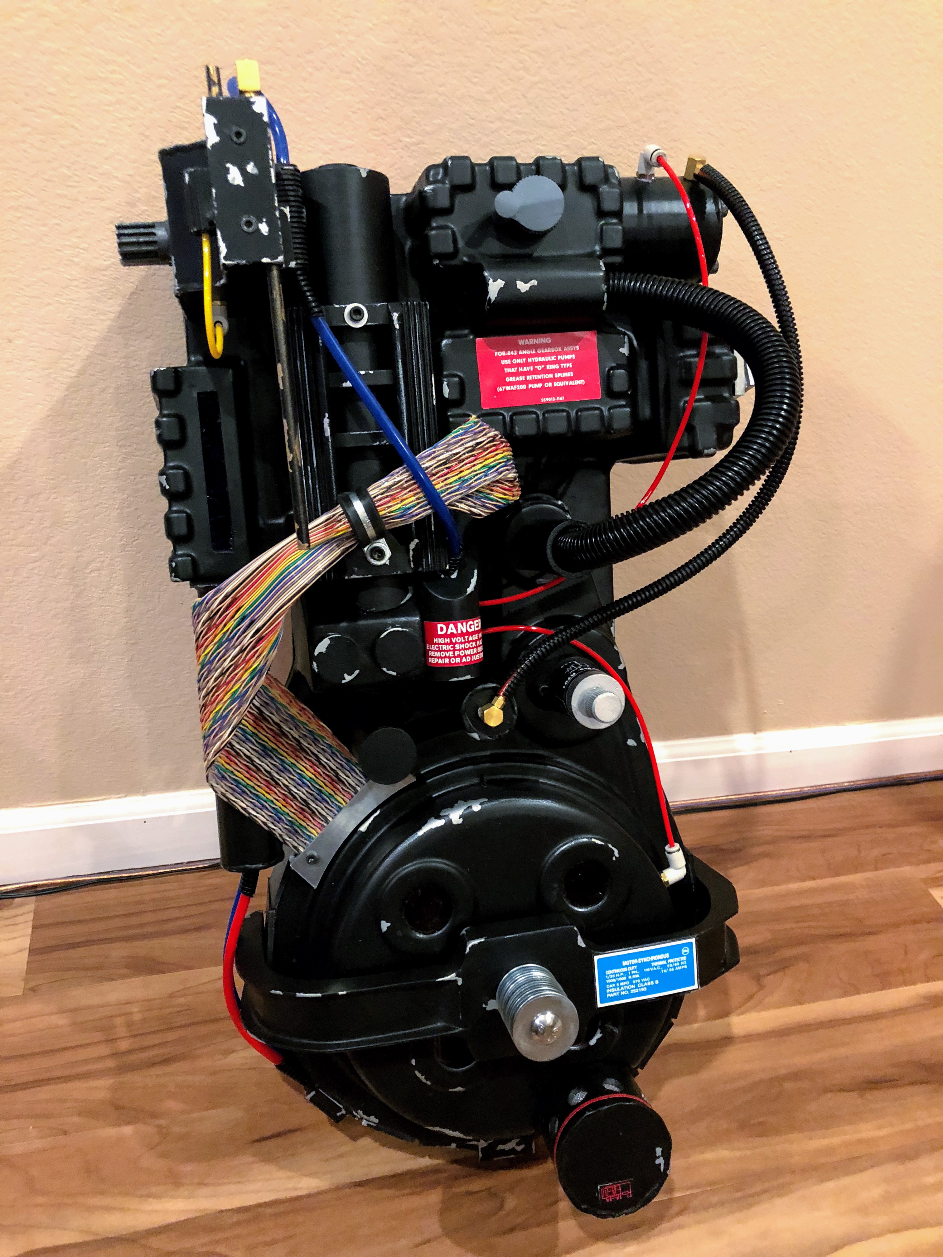
The completed pack in all its glory!
I am very pleased with how this pack turned out. I have a few gripes, but nothing that is noticeable or detracts from the finished product. The beautiful thing is my plan to make everything modular worked, so I can easily replace pieces I don’t like with better versions. I have not weighed the pack, but it feels like it is a just over ten pounds without the ALICE pack, gun, or electronics. I read a few packs have ended up closer to fifty pounds or more, so I am pleased this is much lighter. I’ll be adding a decent amount of weight to it as I continue working on it, so it should remain comfortable to pick up and wear or to display even with the full kit.
I always learn something new as I work on big projects like this. One thing I definitely would have done differently is test fitting everything, screws and all, before doing any finishing work. Every issue I encountered that actually threatened a finished part involved a screw or a drill bit. Learning holes were too small or a hole needed to be drilled after finishing the parts meant drilling into the painted pieces. Hours of work could have gone out the window with one bad move. Luckily nothing that bad occurred, but lesson learned. Test fitting also would have helped my build progress smoothly. When I did test the assembly, that was when I noticed I was missing small things, like the Legris straight connectors next to the PPD.
Overall, this build was a ton of fun. It required a few months of research and planning followed by a little over two weeks of building. I tried new airbrush and finishing techniques. I could have done a lot of that better, but I’ll keep practicing and continue to improve this pack with new parts as I go. For now, it’s ready for its ALCIE frame and I need to plan and source my electronics components.
Tools and Materials
Sourcing Materials
The largest parts of this build came from Studio Creations (the shell) and my 3D printer. However, numerous other little bells and whistles adorn the pack. Here is where I bought them:
- Socket Cap Screws (alls sizes), MDF, and all other hardware
- Home Depot
- Had the best selection and availability for screws in my area and bags were about $0.50.
- Brass rod for the Ion Arm was in the plumbing aisle; it’s a brass rod for a toilet for $2.50!
- They sell 4’ x 2’ project boards of MDF and plywood for ~$5/board.
- Aluminum used for the brackets came from a short angle piece sold as useful for bed frames.
- Home Depot
- Clippard and Legris Parts
- The Clippard barbs and elbows were sourced from gbfans.com.
- Vinyl Tubing
- Finding each color in the proper OD can be a pain in the neck, so I just sourced them from gbfans.com, which has pre-cut lengths for pack builds.
- Wire Loom
- I bought 20’ of 3/4” split loom from Amazon for $12.
- It has a split, but I wanted it this way so I could feed vinyl tubing through it from the gun to the pack. This is what I did for wiring the ghost trap’s pedal to the trap and I wanted to do the same thing here, eventually.
- I got the 1/4” from gbfans.com for a few dollars when ordering the other items.
- I bought 20’ of 3/4” split loom from Amazon for $12.
- Ribbon Cable
- I used GB2-style ribbon cable from gbfans.com.
- I also used gbfans.com’s aluminum ribbon cable clamp, but I later found them in the automotive and hobby section of the “hard to find” section of the screws, bolts, and hardware aisle at Lowes.
- Paints
- I used Rustoleum spray paints, but I have heard Krylon might be better for this sort of project. There wasn’t any available in my area in the right colors and finishes.
- Model Master’s metalizer paints, specifically Aluminum Plate (Buff) was used for the base coat on many parts and came from a local hobby shop.
- Hatchbox Black PLA
- Purchased on Amazon for $20/spool.
- I used just one spool of PLA for my parts.
My Tools
This project did not require anything outrageous or special. The 3D printer could be considered a specialty item, but more and more I feel like it pays for itself in my home. I use it constantly, it got me involved in 3D design, and it has even produced replacement parts for repairs around my house.
- Airbrush
- My airbrush is a basic kit from Amazon: https://www.amazon.com/Master-Airbrush-Multi-purpose-Dual-action-Compressor/dp/B001TO578Q/
- X-Acto Knives
- Nothing special here.
- Alvin vinyl self-healing cutting mats
- Picked up a huge 2’ x 3’ mat for $30 on Amazon when some sellers were undercutting each other on them. Well worth the money even at their usual price of $50-60.
- Dremel Rotary Tool
- Just your average cordless Dremel tool. One of the first tools I ever bought, largely due to how often I used my dad’s ages ago to make Pinewood Derby cars. It’s old and the abttery doesn’t last long anymore, but it’s indispensable for the sanding and cutting wheels.
- Bondo Spot Putty / Body Filler and Putty Knife
- I keep some around and use them in a lot of projects.
- Milwaukee Power Drill with Step Bits
- Useful for a million, mostly obvious, reasons. I drilled a lot of holes.
- Step bits are a necessity for drilling clean, round holes into plastic and PLA.
- Maker Select v2.1 3D Printer
- This is my Wanhao i3 Duplicator clone that I use for all my 3D printing today.
- I have modified it with various 3D printed replacement parts.
- Simplify3D
- I tried it and found it to be a much more useful slicer than Cura and other free slicers, at least for my projects.
- I often use Simplify3D’s multiple processes to make it possible for me to print big plates of models with different settings, change infill mid-print, and more.
- Onshape
- I used this free CAD web application to model the custom pieces of the pack.
- A Basic Band Saw
- A jigsaw would have worked as well, but the band saw made cutting the motherboard and bumper pieces much easier.
- Miter Box and Hacksaw
- A cheap miter box and a hacksaw did wonders for cutting pipes at various angles as needed.
Final Gallery
